High strength honeycomb structure, method of molding the same, and honeycomb structure converter

a technology of honeycomb and structure, which is applied in the direction of machines/engines, ceramic extrusion dies, chemical/physical processes, etc., can solve the problems of insufficient enhancement of isostatic strength, and inability to effectively suppress etc., to achieve the effect of suppressing the decrease in isostatic strength and/or canning strength

Active Publication Date: 2004-10-21
NGK INSULATORS LTD
View PDF15 Cites 33 Cited by
  • Summary
  • Abstract
  • Description
  • Claims
  • Application Information

AI Technical Summary

Benefits of technology

[0007] The present invention has been developed in consideration of the above-described problems heretofore, and aims at providing a honeycomb structure capable of suppressing a decrease in isostatic strength and / or canning strength attendant on the thinning of the honeycomb structure, and providing a honeycomb structure converter thereof.
[0008] Another aim of the present invention is to provide a molding method which can suppress a decrease in isostatic strength and / or canning strength in providing the honeycomb structure.
[0009] As a result of intensive studies by the present inventors, it has been found that a thickness. (TY) of a partition walls whose longitudinal direction is one direction (Y-direction) in a section perpendicular to an axial direction of the honeycomb structure is greater than that of other partition walls, and accordingly the isostatic strength which is a strength against isotropic pressurizing is enhanced. Furthermore, it has been found that the thickness of the partition walls in a predetermined part of the partition walls whose longitudinal direction is the Y-direction, is increased, and accordingly breakage in the canning can be reduced.
[0034] FIGS. 1(a), 1(b) are schematic diagrams showing one embodiment of a honeycomb structure according to the present invention. As shown in FIGS. 1(a), 1(b), a honeycomb structure 1 according to the present invention has a number of cells 3 partitioned by partition walls 2 and extending through an axial direction. An important characteristic of the present invention is that thickness of a partition walls 2Y whose longitudinal direction is one direction (Y-direction) is greater than that of partition walls 2X whose longitudinal direction is the other direction, for example, an X-direction in FIG. 2(b) in a section of the honeycomb structure. By constituting the honeycomb structure 1 in this manner, and preferably extrusion molding in such a manner that the Y-direction is a direction of gravity, an isostatic strength is enhanced. It is an amazing effect that thickening of a partition walls in one direction enhances the isostatic strength which is a strength against isostatic pressurizing from an outer periphery. A reason for this is supposedly that deformation of the partition walls 2 during the period between extruding and firing is inhibited by the above-described constitution to produce the honeycomb structure as designed, and therefore a stress concentration part by the deformation of the partition walls 2 can be eliminated.
[0054] Next, the invention of a method of molding the honeycomb structure will be described. According to the molding method of the present invention, there is provided an extrusion method suitable for molding the above-described honeycomb structure. The molding method of the present invention is characterized by the extrusion molding such that the Y-direction in the above-described honeycomb structure is the direction of gravity, that is, perpendicular. Accordingly, even when the partition walls are thin in their eintirety, the strength of the thicker partition walls 2Y is higher, therefore deformation by its own weight at the time of extrusion can be inhibited, a stress concentrated place can be inhibited from being generated, and the deterioration of the isostatic strength can be suppressed.
[0058] In the present invention, a method of cooling the molded body extruded from the die 22 is not especially limited, and the methods such as air cooling, and water cooling by spraying are usable. The molded body may also be passed in water and quenched. It is to be noted that depending on a molding temperature, extruding speed, type and amount of additives, in the extruding method of the present invention the honeycomb structure can be obtained as designed without any deformation of the partition walls in the cooling at room temperature without forced cooling.

Problems solved by technology

However, the decrease in isostatic strength attendant on the further thinning of the partition walls cannot sufficiently be suppressed even by these structures, and the decrease in canning strength cannot effectively be suppressed.
However, although a certain effect is fulfilled in prevention of chipping at the time of handling in this ceramic honeycomb structure, the isostatic strength is not enhanced sufficiently, and the decrease in canning strength cannot effectively be suppressed.

Method used


Image

  • High strength honeycomb structure, method of molding the same, and honeycomb structure converter
  • High strength honeycomb structure, method of molding the same, and honeycomb structure converter
  • High strength honeycomb structure, method of molding the same, and honeycomb structure converter

Examples


example 1

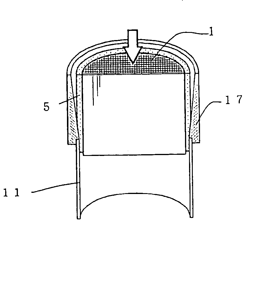
[0068] A predetermined amount of each of raw material powders of talc, kaolin, and aluminum hydroxide was weighed, and thereafter mixed to obtain a raw material batch. Next, in the kneading step, 4% by mass of methyl cellulose with respect to 100% by mass of the raw material batch, and additive water were added to the obtained raw material batch, and kneaded by a kneading device to obtain the kneaded material. The temperature of the kneading device was controlled so as to keep the kneaded material at 10.degree. C. in this kneading step. Next, the obtained kneaded material was deaerated through a vacuum chamber, and kneaded again to prepare a columnar puddle. The columnar puddle was charged into the extrusion molding machine, and extruded in such a manner that the Y-direction was the direction of gravity (perpendicular direction) and the axial direction is the horizontal direction to obtain a honeycomb molded body A. Next, moisture of the honeycomb molded body A was removed by dielec...

examples 2 to 6

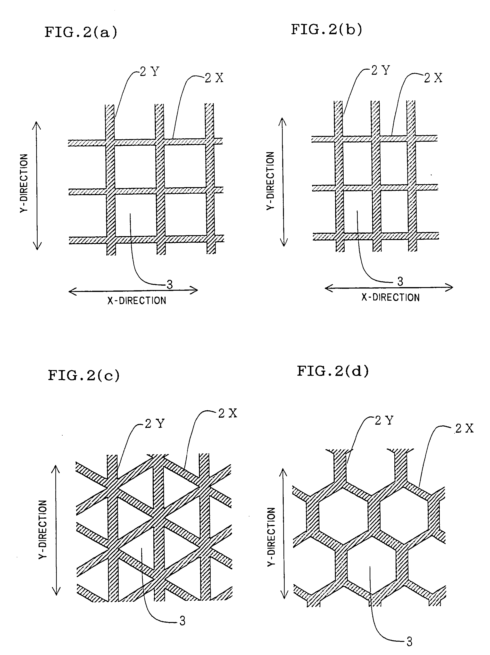
[0069] Honeycomb structures B to F were prepared as Examples 2 to 6 in the same manner as in Example 1 except that the respective thicknesses (TY) of all the partition walls indicating the perpendicular direction at the time of extrusion were set to about 107 .mu.m (about 4.2 mil), about 115 .mu.m (about 4.5 mil), about 125 .mu.m (about 4.9 mil), about 135 .mu.m (about 5.2 mil), and about 142 .mu.m (about 5.6 mil)

example 13 and 14

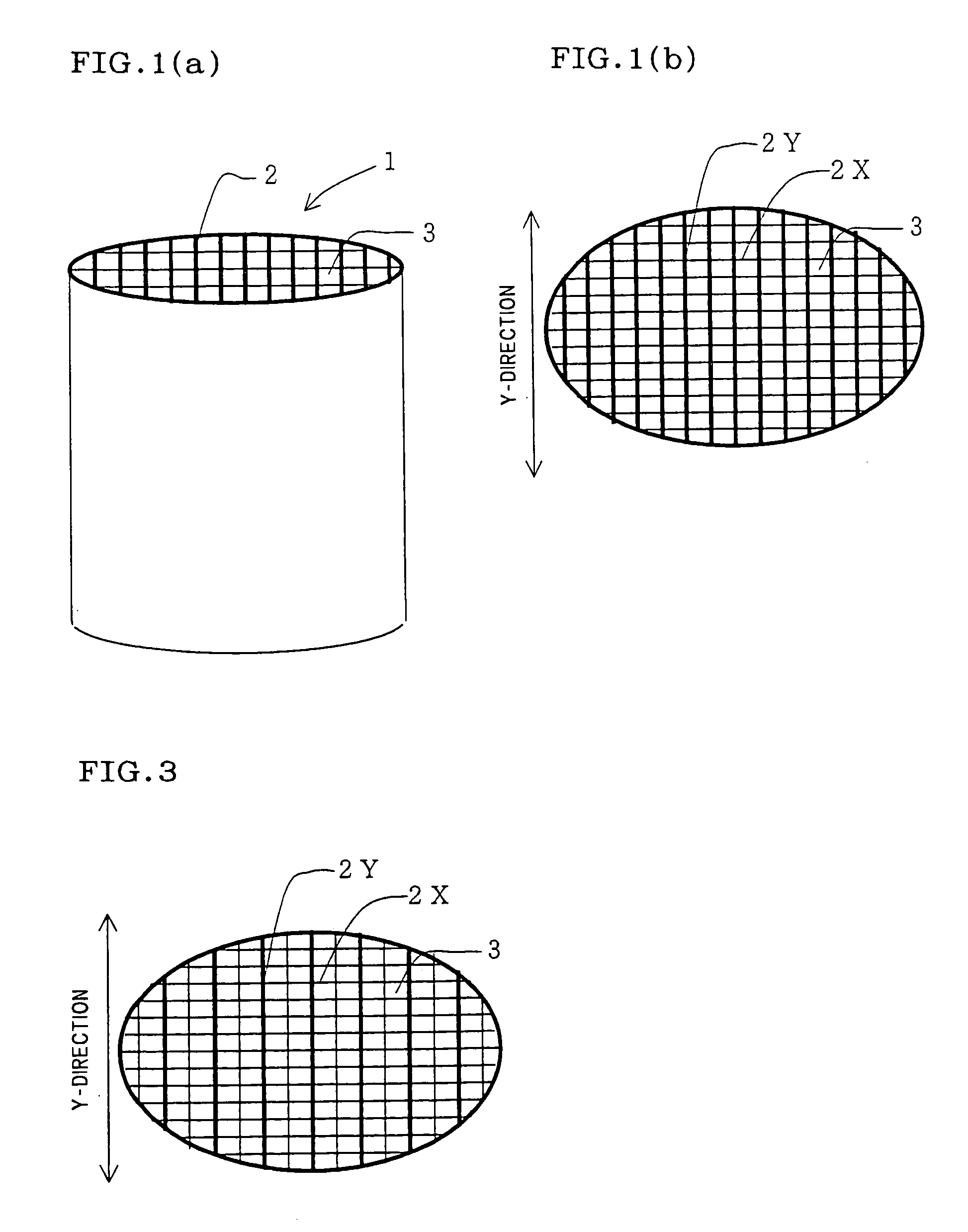
[0080] The honeycomb structure was prepared in the same manner as in Example 7 except that the sectional shape of the honeycomb structure was made to an elliptic shape having a long diameter of 125.0 mm, a short diameter of 80.0 mm, and a length of 100 mm, and the angles of the points O.sub.1 and P.sub.1 and the partition wall thicknesses were set to the angles and thicknesses shown in Table 2.


PUM

PropertyMeasurementUnit
thicknessaaaaaaaaaa
thicknessaaaaaaaaaa
stress concentrationaaaaaaaaaa

Abstract

There are provided a honeycomb structure capable, of suppressing a decrease in isostatic strength attendant on the thinning of the honeycomb structure, a honeycomb structure converter thereof, and a method of manufacturing the honeycomb structure. There is provided a honeycomb structure 1 having a number of cells 3 partitioned by partition walls 2 and extending to a axial direction. There are the honeycomb structure wherein a thickness (TY) of a partition walls (2Y) whose longitudinal direction is one direction (Y-direction) in a section perpendicular to the axial direction of the honeycomb structure 1 is greater than that (TX) of a partition walls (2X) whose longitudinal direction is the other direction; and a honeycomb structure converter thereof. There is provided a method of molding the above-mentioned honeycomb structure. That is the method of molding honeycomb structure wherein the honeycomb structure is extrusion molded such that the Y-direction is a direction of gravity.

Description

[0001] The present invention relates to a honeycomb structure having a high strength, particularly to a honeycomb structure which shows a satisfactory isostatic strength and / or canning strength even with a small average thickness of partition walls, and to a honeycomb structure converter using the honeycomb structure. The present invention further relates to a method of molding a honeycomb structure showing a satisfactory isostatic strength and / or canning strength.[0002] A honeycomb structure has been broadly used in a filter, a catalyst carrier, and the like, especially frequently used as a catalyst carrier in a catalytic converter for purifying an exhaust gas of an internal combustion engine such as an automobile engine, as a filter for purifying an exhaust gas of a diesel engine, and the like.[0003] When the honeycomb structure is used in the catalyst carrier in the catalytic converter for purifying the exhaust gas of an automobile, exhaust gas regulations have tended to be stren...

Claims


Application Information

Patent Timeline
Patent Type & Authority Applications(United States)
IPC IPC(8): F01N3/02B01D39/00B01D39/20B01D46/00B01D46/24B01D53/86B01D53/94B01J32/00B01J35/04B28B3/20B28B3/26F01N3/28
CPCB01D46/2422Y10T428/24149B01D46/2455B01D46/2466B01D46/247B01D46/2474B01D53/94B01D2046/2477B01D2046/2481B01D2046/2492B01D2046/2496B01J35/04B28B3/269F01N3/2828F01N3/2853F01N2330/06F01N2330/34F01N2330/48F01N2450/02F01N2470/10Y10T428/24165Y10T428/24744B01D46/2451B01D46/2498B01D46/249B01D46/2486B01D46/2488B01D46/2484B01D46/2482B01D46/2492
Inventor KONDO, TAKAHIROICHIKAWA, YUKIHITO
Owner NGK INSULATORS LTD
Why Eureka
Try Eureka