Apparatus and method for generating calibration gas

a calibration gas and apparatus technology, applied in the direction of liquid transfer devices, instruments, liquid handling, etc., can solve the problems of destroying the gas sample, the sensor will gradually lose sensitivity, and the gas molecules will change permanently, so as to achieve accurate gas concentration and low cost

Active Publication Date: 2005-01-06
INDUSTRIAL SCIENTIFIC CORPORATION
View PDF4 Cites 98 Cited by
  • Summary
  • Abstract
  • Description
  • Claims
  • Application Information

AI Technical Summary

Benefits of technology

It is therefore a primary object of the invention to provide an apparatus and method for generating a calibration standard gas at low cost using a device that is portable, compact, and capable of generating gas on demand with accurate gas concentrations.
Such a miniature gas cylinder can make a large quantity of gas. For example, a miniature cylinder having a 10 ml water capacity holds 340 ml CO gas when the gas pressure is 500 psi, which is about 60 times the quantity of CO in a standard disposable cylinder filled with 58 liters (2 ft3) of 100 ppm gas under the same pressure. Because of the very limited quantity of the gas contained in the miniature cylinder, it will not endanger human life if it accidentally leaks out. In a confined space as small as 10 m3, the highest concentration caused by a leaking cylinder is 34 ppm by volume, which is low and safe. A 10 ml cylinder filled with pure methane under 2000 psi holds a quantity of gas that is equivalent to 1360.5 ml at 1 atmosphere. When diluted to the same confined space, the gas concentration will be 136 ppm by volume, which is far below its lower explosion limit of 5%, or 50,000 ppm by volume.
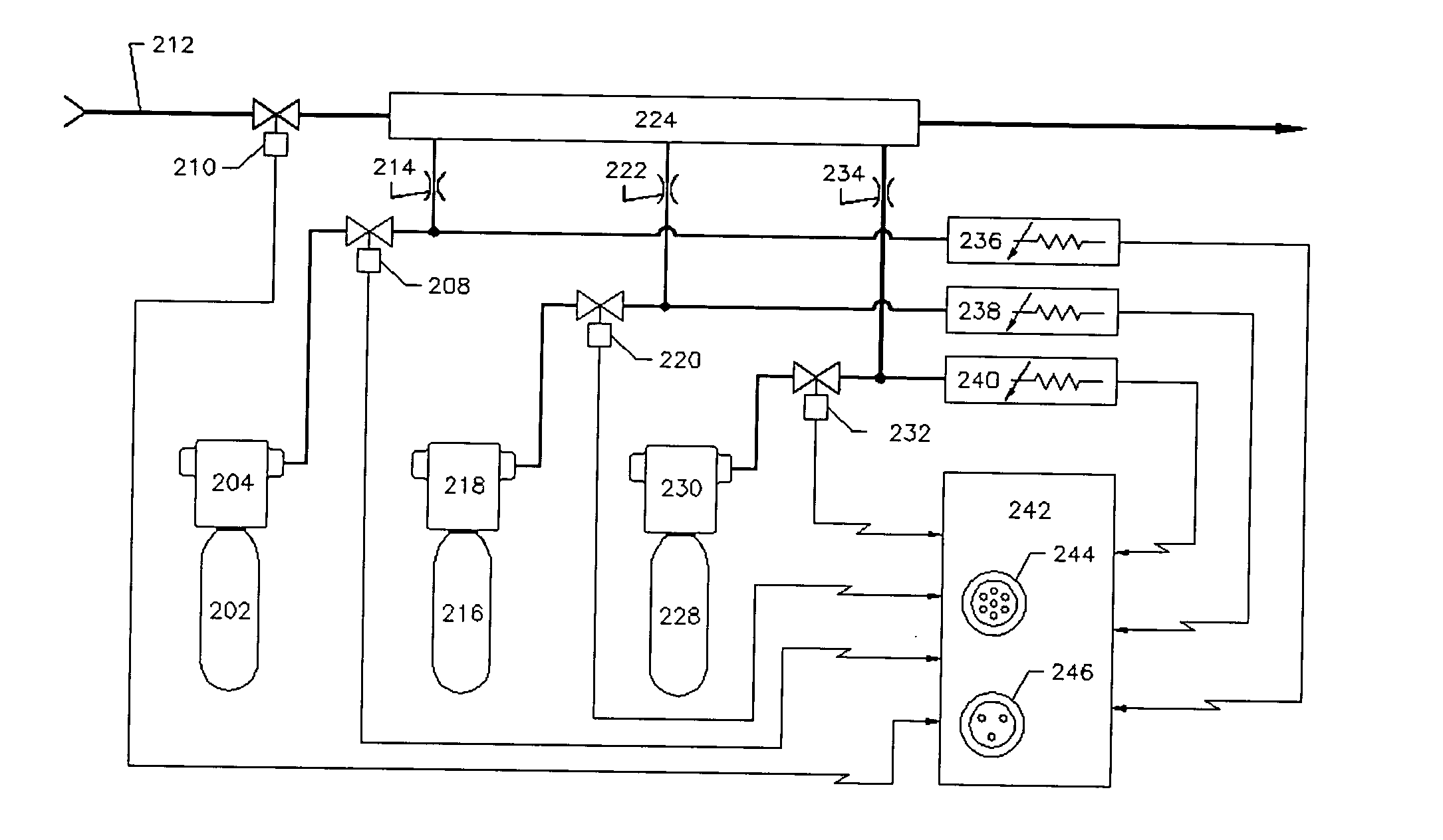
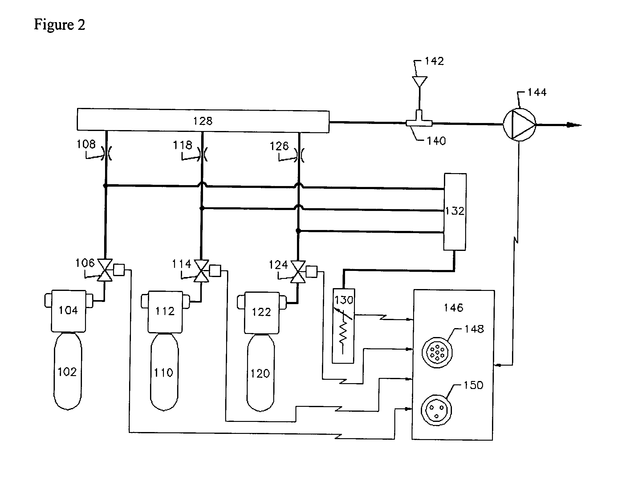
Gas generators built with miniature gas cylinders can be very compact. They can be designed as portable instruments for use with portable gas detection instruments. They can also be incorporated into fixed gas detection systems for conducting regular bump testing and automatic calibration. Regular testing and calibration gases have been a large expense to instrument owners and especially to the owners of fixed systems as a field trip is often involved. Considering the large quantity of calibration gas that a miniature cylinder can supply, a gas generator made according to the invention can work as an automated, stand alone test station. The generator can have multiple cylinders, with each cylinder being a one piece miniature cylinder filled with concentrated gas for generating low concentration gases used to test and / or calibrate multiple instruments. There is a trend in the gas detection industry of making computerized calibration / test stations; a number of instruments, including single gas detectors and multiple gas detectors, can be docked on the station. The computer recognizes each instrument and only gases of interest are introduced to the instrument. Docking stations conduct gas testing and calibration on a more frequent basis, thus gas usage has greatly increased. Gas generators built according to the invention meet this challenge, and can be installed in small offices without safety concerns.

Problems solved by technology

Some types of sensors react with the gas and cause a permanent change in gas molecules and are destructive to the gas sample.
Typically a sensor will gradually lose sensitivity due to environmental or aging effects.
In some severe weather conditions, a sensor can lose sensitivity within a very short period of time.
For example, a galvanic type oxygen sensor can fail suddenly when the capillary hole, through which oxygen diffuses into the sensor cell, is blocked by water or dust.
Some electrochemical sensor can fail rapidly due to leakage of electrolyte.
Catalytic bead sensors that are used for detecting combustible gases, can lose sensitivity without any indication after exposure to silicone compounds which poison sensors by building up a solid coating over catalyst sites which blocks gas reactions.
The use of a defective, low sensitivity instrument is extremely dangerous as it often gives a false, misleading reading, putting human lives and property in great danger.
Sensors can, however, fail between calibrations, and instrument users are advised to verify their instrument functionality prior to each use.
If the gas is unstable or reactive, however, it will have a short life and poor accuracy especially when the concentration is in the low parts per million (ppm) range.
Moreover, pre-mixed gases are very expensive.
Such cylinders are also large in size and are inconvenient to transport and carry in the field.
In spite of simple operation and calculation, normal MFCs can't be used for diluting gas accurately at a dilution ratio greater than 10:1.
Successive dilutions significantly increase error in the final gas concentration, not to mention the inaccurate concentration of the source gas.
According to gas manufacturers, the lower the concentration of a gas in a gas mixture, the higher the error in gas concentration.
A gas can be prepared with a tolerance well within ±1-2% when its concentration is above 1% by volume, but it's difficult to make it better than ±5% when its concentration is below 1000 ppm.
Besides, mass flow controllers are very expensive, gas generators built with mass flow controllers are usually cost prohibitive.
Permeation tubes must be used with precise temperature control ovens or apparatus, which are bulky and expensive.
Although a wide range of permeation rates can be made by varying the length and thickness of the tubes, the normal operating rates range from 5 ng / min to 5 μg / min, or in the parts per billion (ppb) range when diluted to 500 ml / min which is a flow rate typically required for calibrating gas detection instruments in the safety market; they are not, therefore, suitable for gas monitoring applications.
They suffer from poor accuracy, too.
The most used test gases such as carbon monoxide and methane cannot be produced in a reliable, controlled manner through chemical or evaporation processes.

Method used


Image

  • Apparatus and method for generating calibration gas
  • Apparatus and method for generating calibration gas
  • Apparatus and method for generating calibration gas

Examples


Embodiment Construction

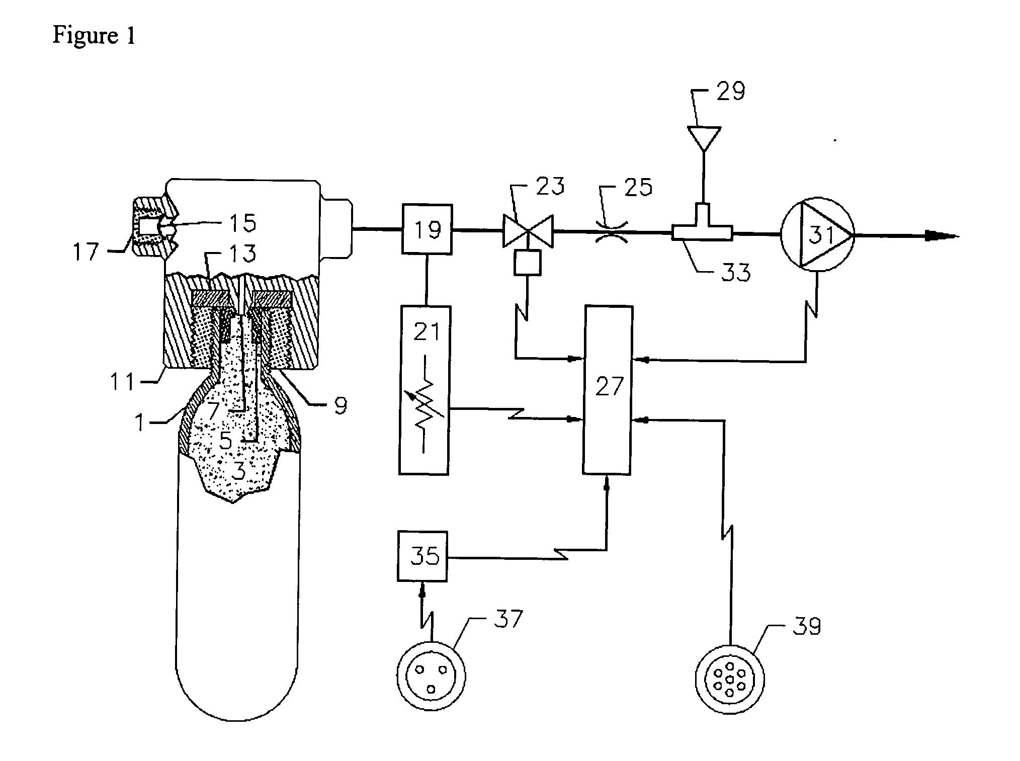
FIG. 1 illustrates a gas generator built with a miniature gas cylinder, or cartridge. The generator includes a gas source, a gas dilution device, and a control system. The techniques used to provide diluted, low concentration gas are basically pneumatic pressure regulation and flow control.

The source of gas includes a miniature gas cylinder, a gas release device and a flow control system. As shown, the gas source is a miniature gas cylinder 1 of no more than 100 ml internal volume containing a compressed, concentrated gas 3, and closed by a welded cylinder cap 5. The cylinder cap 5 is specially constructed with a reduced thickness portion in the center of the cap, which facilitates piercing of the cylinder during installation. Cylinder 1 is held by a threaded neck and seal retainer 9 in a gas cylinder receptacle 11 which includes a piercing device 7 that punctures the reduced thickness portion of cap 5 to release the contents of the cylinder into the receptacle 11. The piercing dev...


PUM

PropertyMeasurementUnit
volumeaaaaaaaaaa
diameteraaaaaaaaaa
diameteraaaaaaaaaa

Abstract

An apparatus and method for generating a low concentration of gas within a carrier gas flow employing one or more miniature one-piece cylinders filled under pressure with a pure gas, or a concentrated gas balanced with an inert gas or gas mixture. Released from the cylinder through a pierced or other controlled opening, the flow of the gas is regulated by a pressure regulator and a micro orifice to be blended into a steady stream of diluent gas, typically ambient air, to form a desired gas concentration. No gas is generated if the pressure of the gas in the cylinder, which is monitored constantly by a pressure transducer, is below a predetermined level. The apparatus can be built into a portable device, or an automated docking station (or calibration station) for testing and calibrating gas detection and monitoring instruments, or into a fixed gas detection system for performing such functions.

Description

BACKGROUND OF THE INVENTION 1. Field of the Invention The invention relates to an apparatus and method employing one or more miniature one-piece gas cylinders, for producing low concentration gases for testing and / or calibrating gas monitoring instruments. 2. Description of Related Art Gas detection instruments are widely used to safeguard human lives and property in various industries in, for example, potentially explosive environments such as mines having methane (CH4) pockets, confined spaces where there exist toxic gases such as carbon monoxide (CO) and hydrogen sulfide (H2S), or a deficiency of oxygen, and chemical process plants where emissions may include sulfur oxide (SOx), nitrogen oxide (NOx), chlorine (Cl2), etc. The heart of each instrument is comprised of sensors that convert chemical energy to electrical energy. The most common sensors include metal oxide semiconductor (MOS) sensors, thermal conductivity sensors, catalytic bead sensors, electrochemical sensors, inf...

Claims


Application Information

Patent Timeline
Patent Type & Authority Applications(United States)
IPC IPC(8): G01N21/27G01N33/00
CPCG01N33/0006G01N21/278
Inventor PENG, WENFENGGREEN, DAVID C.STEWART, ROBERT G.
Owner INDUSTRIAL SCIENTIFIC CORPORATION
Why Eureka
Try Eureka