Pump for low flow rates

Inactive Publication Date: 2005-01-13
ROCHE DIABETES CARE INC
View PDF11 Cites 37 Cited by
  • Summary
  • Abstract
  • Description
  • Claims
  • Application Information

AI Technical Summary

Benefits of technology

[0023] It is important for the desired pump function that there is no direct contact between the sorbent and the capillaries/pores of the wettable membrane to prevent direct transfer of liquid by this means. On the contrary, in order to achieve low flow rates that remain constant over long periods it is necessary that firstly evaporation of transport liquid occurs and that the evaporated transport liquid is taken up from the gas phase by the sorbent. This can be achieved by spacing apart the wettable membrane and the sorbent such that there is no direct fluid contact. Furthermore it is possible to use one (or also several) non-wettable membrane(s) which are preferably located directly next to the wettable membrane. With such a membrane the sorbent can also be in direct contact without generating a fluid short circuit. Such an arrangement also enables the use of a liquid sorbent such as a highly concentrated or saturated salt solution. Another method is to modify a region of the wettable membrane that faces away from the transport liquids or faces the sorbent in such a manner that the membrane cannot be wetted and thus adopts the function of a second non-wettable membrane. Such a modification of the membrane can for example be achieved by a plasma reaction. With embodiments containing membranes which have a wettable region and a non-wettable region

Problems solved by technology

Furthermore it has turned out that such pumps do not operate reliably enough in the low pumping range when used for long-term applications and in particular it is difficult to avoid large variations in the flow rates.
However, this has the disadvantage that the pressure time course is non-linear.
However, the transport liquids preferably contain

Method used


Image

  • Pump for low flow rates
  • Pump for low flow rates
  • Pump for low flow rates

Examples


Embodiment Construction

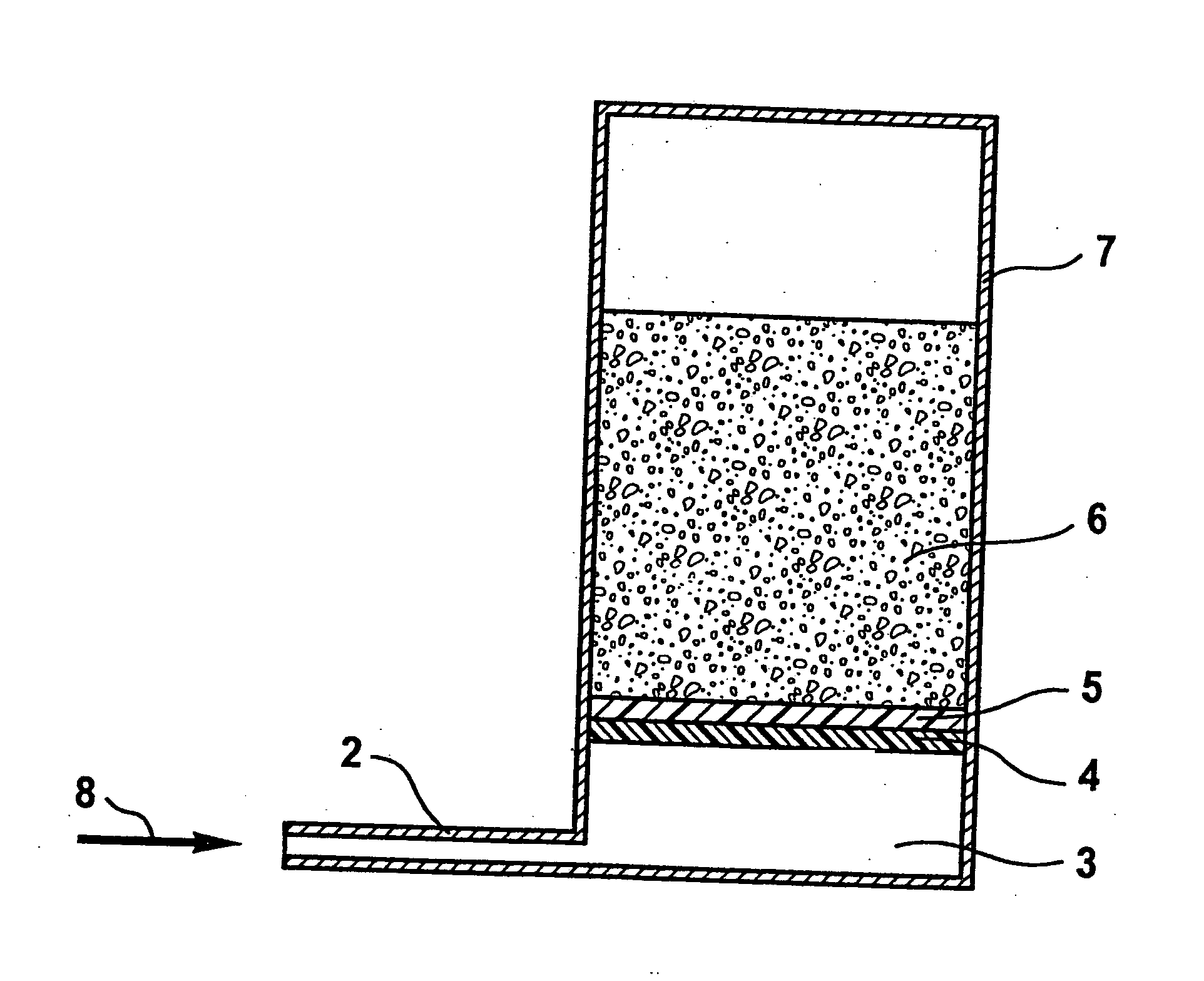
[0038]FIG. 1 shows a cross-section through a pump according to a first embodiment. The arrangement shown has a channel (2) having a diameter of 100 μm in which a transport liquid is located. Water was chosen as the transport liquid in the case shown. The channel is closed with a wettable membrane (4) in a region of the transport channel with an enlarged cross-section. In the present case a BTS 65 from the Memtec Company (now: USF Filtration and Separations Group, San Diego, Calif., USA) (PESu hydrophilized with hydroxypropyl cellulose) was used as the membrane. This very hydrophilic membrane is asymmetric and has pores in the range from about 10 μm on one side and 0.1 μm on the other side. The side with the larger pores faces the liquid. A non-wettable membrane made of expanded PTFE is located above the wettable membrane (4). The non-wettable membrane is mounted on the wettable membrane in such a manner that it completely covers the side of the wettable membrane (4) which faces away...


PUM


Abstract

The present invention concerns a method of producing flow rates of a transport liquid of about 1 to 1000 nl/min. The method provides a pump having a housing defining a space and including a channel and a wettable membrane positioned in the housing, the membrane including a first side facing toward the channel and a second side facing the space. The method further includes at least partially filling the channel with the transport liquid, contacting the wettable membrane with the transport liquid to generate an underpressure in the channel,evaporating the transport liquid at the wettable membrane to remove the transport liquid from the channel and to create an underpressure in the channel, and maintaining a generally constant vapour pressure of the transport liquid in the space.

Description

CROSS-REFERENCE TO RELATED APPLICATIONS [0001] The present application is a divisional of U.S. patent application Ser. No. 09 / 884,879, filed on Jun. 19, 2001, which claims priority to DE 100 29 453.7 filed on Jun. 21, 2000.BACKGROUND AND SUMMARY OF THE INVENTION [0002] The present invention concerns a pump for flow rates in the range from about 1 to 1000 nl / min. The pumps according to the invention are particularly suitable for applications in the field of medical diagnostics such as microdialysis or ultrafiltration. [0003] A pump is claimed for low flow rates which having channel which is at least partially filled with a transport liquid and a membrane that can be wetted by the transport liquid which closes one opening of the channel and through which evaporation can take place. There is a space on the opposite side of the membrane to the transport liquid which has an essentially constant vapour pressure of the transport liquid. The invention also encompasses microdialysis and ultr...

Claims


Application Information

Patent Timeline
IPC IPC(8): A61M1/14B01D61/22B01D67/00F04B17/00F04B43/06
CPCF04B17/00Y10T436/2575F04B43/06
Inventor EFFENHAUSER, CARLOHARTTIG, HERBERTKRAEMER, PETER
Owner ROCHE DIABETES CARE INC
Why Eureka
Try Eureka