Device and method for vacuum film formation

Inactive Publication Date: 2005-01-13
NEC CORP
View PDF19 Cites 71 Cited by
  • Summary
  • Abstract
  • Description
  • Claims
  • Application Information

AI Technical Summary

Benefits of technology

[0030] In the battery electrode fabrication method of the fourth aspect, the blocking member intermittently blocks movement of the evaporated substance from the evaporation source to the substrate. As a result, an active material film of a desired shape of pattern can be stably formed with higher controllability. In the present invention, the blocking member disposed apart from the substrate is used instead of the mask used in the conventional technique. This solves the problems such as the displacement of the film, the contamination caused by the peel-off of the evaporated substance, attached onto the mask, during the carriage, and the cut-off of the substrate during the deposition, which are involved in the conventional technique. I

Problems solved by technology

In the technique described in JP-A-1984-6372, it is difficult to deposit the evaporated substance on the specified position of the metallic stripe belt because there is a large possibility that the mask and the metallic stripe belt have slack or bending due to the influences from the gravity and the tension by the sprocket.
In the technique described in JP-A-2000-183500, although the mask and the substrate are carried along the guide roll (evaporation roll) for effecting the pattern-deposition, the evaporated substance is deposited onto the mask during the iterated deposition process, whereby the deposited, evaporated substance may possibly be peeled off during the carriage to cause contamination or pollution.
In addition, there are other problems that the mask is likely to be displaced or bent during the carriage, similarly to the technique described in JP-A-1984-6372.
Moreover, in the patterning by using th

Method used


Image

  • Device and method for vacuum film formation
  • Device and method for vacuum film formation
  • Device and method for vacuum film formation

Examples


Example

FIRST EXAMPLE

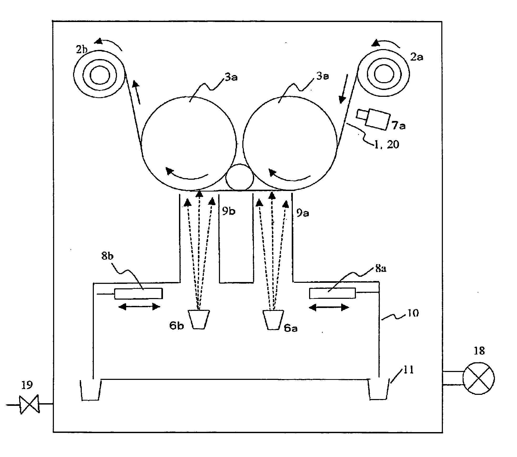
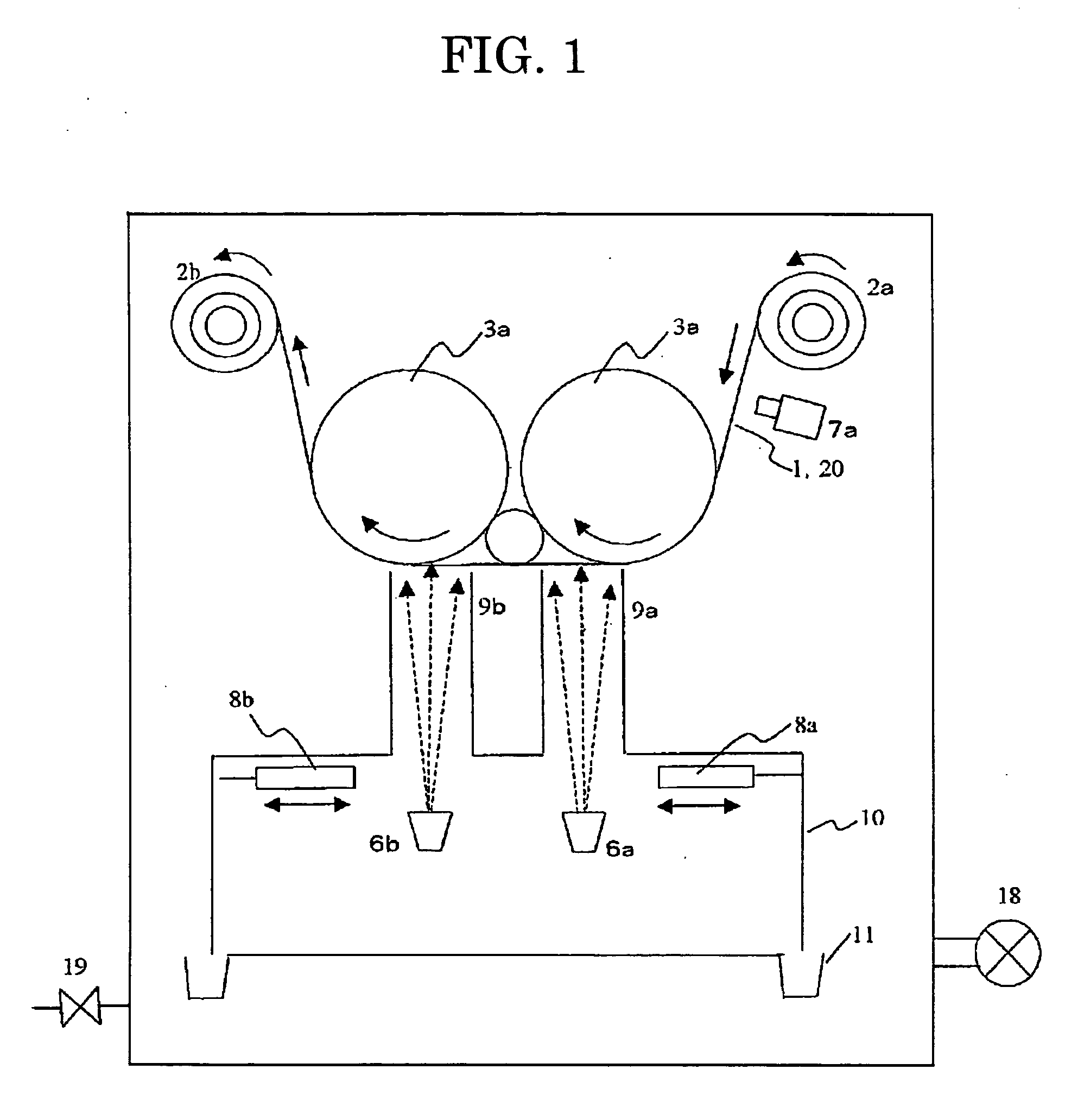
[0056] In the first example, a process for patterning a film made of silicon-lithium alloy (SiLi) on a patterned graphite as an anode of a non-aqueous electrolyte secondary battery by using the vacuum deposition apparatus of FIG. 1 is exemplified, wherein the surfaces of an anode collector (copper film) were patterned one by one. It is to be noted that evaporation sources (6a to td) each including the silicon-lithium alloy (SiLi) were used in the following examples and the comparative examples.

[0057] As shown in FIG. 4, a copper foil 20 having a length of about 2000 meters and a thickness of 10 μm was used as a flexible substrate constituting an anode collector, on which a layer 21a made of graphite was deposited. This graphite layer 21a was obtained by admixing polyvinylidene fluoride, wherein graphite powder was dissolved in N-methyl-2-pyrrolidone as a binder, and a conductivity-affording agent to obtain a paste, coating the resultant paste on both surfaces of the c...

Example

FIRST COMPARATIVE EXAMPLE

[0066] In the first comparative example, a pattern mask and a copper foil are overlapped and carried in synchrony with each other, to try electrode patterning on the copper foil through the opening of the pattern mask.

[0067] The copper foil 20 on which graphite was formed is similar to that used in the first example. It is to be noted that alignment marks (holes) 22 are appropriately provided therein for alignment with the pattern mask. A Ni-plated copper foil 24, obtained by forming openings 22 in a copper foil, which was about 20 μm thick, 0.24 m wide and about 2000 m long, and plating the surface of the copper foil with nickel, was used as the pattern mask. FIG. 6(a) shows the pattern of the graphite layer on the top surface of the copper foil, whereas FIG. 6(b) schematically shows the pattern mask for patterning on the top side of the copper foil. The pattern mask is also provided with alignment marks 22 for alignment with the copper foil 20. FIG. 7(a)...

Example

SECOND EXAMPLE

[0077] In the second example, a vacuum deposition apparatus for patterning a film made of silicon-lithium alloy (SiLi) on a patterned graphite as an anode of a non-aqueous electrolyte secondary battery by using a vacuum throughout the process, wherein both the surfaces of an anode collector (copper film) were patterned, and a method for using the apparatus will be described.

[0078] The copper foil attached with graphite was similar to that used in the first example. FIG. 9 schematically shows the internal configuration of the vacuum evaporation apparatus for forming a SiLi layer 21b on the specified positions (graphite layers 21a) of both the top and bottom surfaces of the copper foil 20 shown in FIG. 4. The rollers for procedures from the feed to the take-up of the copper foil 20 include a feed roller 2a for feeding the copper foil 20, two guide rollers 3a provided for accurately moving the copper foil 20 to accurately deposit evaporated substance from the evaporatio...


PUM

PropertyMeasurementUnit
Shapeaaaaaaaaaa
Electrical conductoraaaaaaaaaa

Abstract

A vacuum deposition apparatus is used for deposit evaporated substance from evaporation sources (6a and 6b) on the desired position of a flexible substrate (1). While the flexible substrate (1) is carried using rollers in a vacuum, shutters (8a and 8b) are opened and closed to control the movement of the evaporated substance via openings. A film having a desired shape of pattern is formed on the flexible substrate (1) with higher controllability.

Description

TECHNICAL FIELD [0001] The present invention relates to a vacuum deposition apparatus and a vacuum deposition process for pattern-depositing a film on a substrate while carrying the substrate in a vacuum. BACKGROUND TECHNOLOGY [0002] Due to widespread use of mobile terminals such as cellular phones and notebook personal computers, the role of the secondary batteries used for the power source thereof has increased importance. The secondary batteries are requested to have smaller size, lighter weight and higher capacity along with the stronger demand for larger-capacity, higher-speed communications and higher-speed transmission of color moving pictures. [0003] For achieving the higher capacity of the secondary batteries, it is important to develop the electrodes, especially the anode active material thereof. Lithium-ion secondary batteries, wherein a metallic lithium foil is formed as an anode active material on a conductive substrate such as a copper foil by using a vacuum deposition...

Claims


Application Information

Patent Timeline
IPC IPC(8): C23C14/04C23C14/18C23C14/56H01M4/04
CPCC23C14/042C23C14/044C23C14/18H01M4/0421H01M4/04H01M4/0404H01M4/0409C23C14/562Y02E60/10C23C14/04
Inventor UTSUGI, KOJIYAMAMOTO, HIRONORIMIYACHI, MARIKOMIURA, TAMAKIMORI, MITSUHIROBANNAI, YUTAKAYAMAZAKI, IKIKO
Owner NEC CORP
Why Eureka
Try Eureka