Unlock instant, AI-driven research and patent intelligence for your innovation.

Multi-step process for etching photomasks

Inactive Publication Date: 2005-01-13
APPLIED MATERIALS INC
View PDF23 Cites 34 Cited by
  • Summary
  • Abstract
  • Description
  • Claims
  • Application Information

AI Technical Summary

Benefits of technology

In yet another aspect, a method is provided for processing a reticle including positioning the reticle on a support member in a processing chamber, wherein the reticle comprises a metal photomask layer formed on a silicon-based substrate, and a patterned resist material deposited on the anti-reflective coating, etching the metal photomask layer with a proce

Problems solved by technology
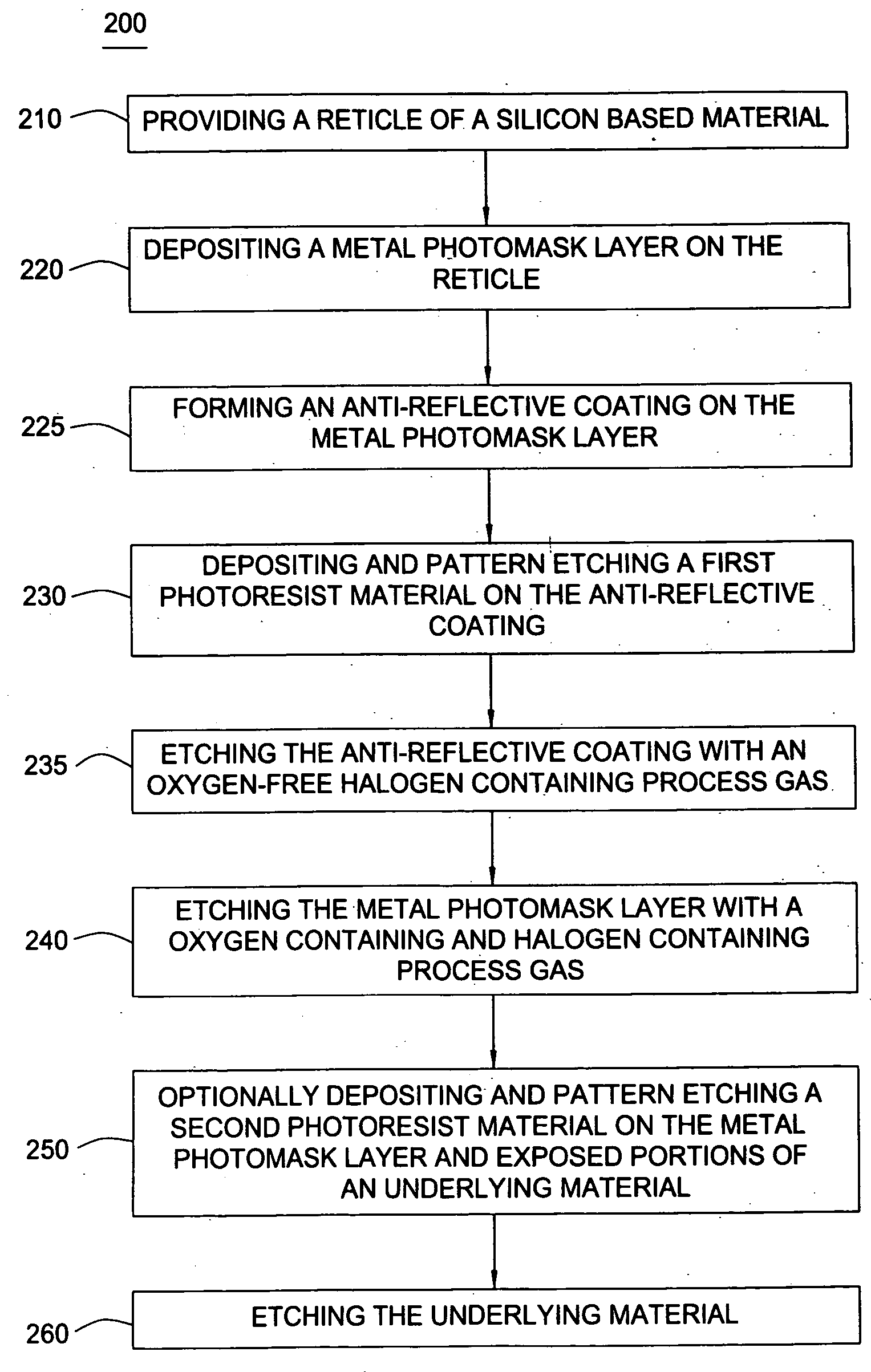
Conventional etching processes, such as wet etching, tend to etch isotropically, which can result in an undercut phenomenon to occur in the metal layer below the patterned resist.
The undercut phenomenon can produce patterned features on the photomask that are not uniformly spaced and do not have the desired straight, vertical sidewalls, thereby losing the critical dimensions of the features.
Additionally, the isotropic etching of the features may overetch the sidewalls of features in high aspect ratios, resulting in the loss of the critical dimensions of the features.
Features formed without the desired critical dimensions in the metal layer can detrimentally affect light passing therethrough and result in less than desirable patterning by the photomask in subsequent photolithographic processes.
However, dry etching may overetch or imprecisely etch the sidewalls of the openings or pattern formed in the resist material used to define the critical dimensions of the metal layer.
Excess side removal of the resist material results in a loss of the critical dimensions of the patterned resist features, which may correspond in a loss of critical dimensions of the features formed in the metal layer defined by the patterned resist layer.
Further, imprecise etching may not sufficiently etch the features to provide the necessary critical dimensions.
Additionally, the metal layer, particularly the surface of the metal layer, may incorporate contaminants, such as oxygen and nitrogen, which are more sensitive to etching radicals than the metal layer alone, and can result in the loss of critical dimensions.
However, the anti-reflective coating may comprise inorganic matter, and similar to the contaminated metal layer described above, become overetched and result in the loss of critical dimensions.
The loss or gain of critical dimensions of the pattern formed in the metal layer can detrimentally affect the light passing therethrough and produce numerous patterning and subsequent etching defects in the substrate patterned by the photolithographic reticle.
The loss or gain of critical dimensions of the photomask can result in insufficient photolithographic performance for etching high aspect ratios of sub-micron features, and, if the loss or gain of critical dimensions is severe enough, can also result in the failure of the photolithographic reticle or subsequently etched device.
However, polymer-forming compounds may deposit on chamber components and become a source of particulate matter in the processing chamber.
Particulate matter may deposit on the substrate surface and detrimentally affect the etching process as well as subsequent processing.

Method used


Image

  • Multi-step process for etching photomasks
  • Multi-step process for etching photomasks
  • Multi-step process for etching photomasks

Examples


example 1

The reticle is placed in an etch chamber such as the DPS™ metal etch chamber described above. The patterned substrate described above is placed on the cathode pedestal of the etch chamber, and the chamber was maintained at a pressure of about 8 milliTorr. A plasma is generated by applying a source RF voltage to the inductive coil at a power level of about 350 watts. A bias power of 20 watts is applied to the cathode pedestal. The etching of the chromium oxynitride ARC layer occurred for approximately 30 seconds under a total flow of 250 sccm with the following gas flows:

Oxygen (O2), at 0 sccmChlorine gas (Cl2), at225 sccmHelium (He), at 25 ccm

The etching of the chromium photomask layer occurred for approximately 185 seconds under a total flow of 250 sccm with the following gas flows:

Oxygen (O2), at 25 sccmChlorine gas (Cl2), at200 sccmHelium (He), at 25 sccm,

with a ratio of chlorine to oxygen of about 8:1. Measured chromium etch profiles observed from this example indicate a ...

example 2

The reticle is placed in an etch chamber such as the DPS™ metal etch chamber described above. The patterned substrate described above is placed on the cathode pedestal of the etch chamber, and the chamber was maintained at a pressure of about 8 milliTorr. A plasma was generated by applying a source RF voltage to the inductor coil at a power level of about 350 watts. A bias power of 20 watts was applied to the cathode pedestal. The etching of the chromium oxynitride ARC layer occurred for approximately 60 seconds under a total flow of 250 sccm with the following gas flows:

Oxygen (O2), at 0 sccmChlorine gas (Cl2), at225 sccmHelium (He), at 25 sccm.

The etching of the chromium photomask layer occurred for approximately 185 seconds under a total flow of 250 sccm with the following gas flows:

Oxygen (O2), at 25 sccmChlorine gas (Cl2), at200 sccmHelium (He), at 25 sccm,

with a ratio of chlorine to oxygen of about 8:1.

An overetch process of the chromium photomask layer occurred for a...


PUM

PropertyMeasurementUnit
Temperatureaaaaaaaaaa
Fractionaaaaaaaaaa

Abstract

Method and apparatus for etching a metal layer disposed on a substrate, such as a photolithographic reticle, are provided. In one aspect, a method is provided for processing a photolithographic reticle including positioning the reticle on a support member in a processing chamber, wherein the reticle comprises a metal photomask layer formed on a silicon-based substrate, and a patterned resist material deposited on the silicon-based substrate, etching the substrate with an oxygen-free processing gas, and then etching the substrate with an oxygen containing processing gas.

Description

BACKGROUND OF THE INVENTION 1. Field of the Invention The present invention relates to the fabrication of integrated circuits and to the fabrication of photolithographic reticles useful in the manufacture of integrated circuits. 2.Background of the Related Art Semiconductor device geometries have dramatically decreased in size since such devices were first introduced several decades ago. Since then, integrated circuits have generally followed the two year / half-size rule (often called Moore's Law), which means that the number of devices on a chip doubles every two years. Today's fabrication plants are routinely producing devices having 0.15 μm and even 0.13 μm feature sizes, and tomorrow's plants soon will be producing devices having even smaller geometries. The increasing circuit densities have placed additional demands on processes used to fabricate semiconductor devices. For example, as circuit densities increase, the widths of vias, contacts and other features, as well as th...

Claims


Application Information

Patent Timeline
IPC IPC(8): A61N5/00B44C1/22C03C15/00C03C25/68C23F1/00C23F4/00G03C5/00G03F1/00G03F1/80G03F9/00G21G5/00
CPCC23F4/00G03F1/80G03F1/14G03F1/50
Inventor BROOKS, CYNTHIA B.BUIE, MELISA J.STOEHR, BRIGITTE C.
Owner APPLIED MATERIALS INC