[0019] The present invention provides a wide variety of diagnostic and therapeutic functions, including without limitation the following: (i) diagnosing electrical pathways or providing
ablation therapy for cardiac arrhythmias and / or vessels of a body; (ii) dispensing a volume of contrast media from a lumen in a catheter body proximal a distal end of the catheter so that a
distal portion can be guided to a desired location using, for example, standard
fluoroscopy techniques; (iii) providing a compact, adjustable-
diameter loop ablation catheter for selectively creating a relatively uniform
stenosis in a vessel on at least one side of a deployed
stent or adjacent a location scheduled to receive a
stent; (iv) providing a platform for performing electrically-guided cardiac tissue biopsies (e.g., for a myocardial infarct, an SA node, an AV node); and (v) providing electrically-guided delivery of therapeutic agents to a volume of cardiac tissue. In all forms of the present invention an elongated catheter having at least one multi-purpose lumen is readily adaptable to perform each of the forgoing procedures, among others.
[0024] In concert with or following confirmation or validation of the status of myocytes, and without moving a catheter already positioned adjacent a volume of tissue containing such myocytes the inventors hereof believe it beneficial to be able to provide one or more therapeutic agents (e.g., biological, pharmacological, or genetic agents) to said myocytes. Accordingly, the present invention provides a platform to efficiently and accurately deliver such therapeutic agents to a volume of previously targeted cardiac tissue. Such tissue may include, for example, a portion of an MI, an SA node, or an AV node.
[0027] When configured for ablation, the electrodes—upon activation of the
energy source—forming the ablation section disrupt existing electrical pathways by causing a suitable magnitude
radio frequency signal to impinge upon adjacent tissue to form non-conducting lesions. The ablation section can form a loop portion or a distally decreasing diameter
helix wherein the diameter of the
helix is manually adjustable to enhance the
lesion pattern for a given diameter PV. In those embodiments of the present invention having an optional tip portion, the tip provides a relatively linear leader section can have a radio-opaque ring and / or tip portion. The leader and optional tip assist a clinician when navigating the distal portion, for example near a PV or a myocardial infarct (MI) while at the same time guiding the electrodes disposed on the adjustable diameter loop or
helical portion to a location disposed approximately equally from the relatively central portion of the PV or MI.
[0028] Another feature of a catheter fabricated according to the present invention relates a fluid port optionally configured with a one-way valve mechanism that reduces ingress of
body fluid while also focusing the
stream of fluid material emitted therefrom so it impinges upon and about the distal portion of the catheter and the adjacent tissue.
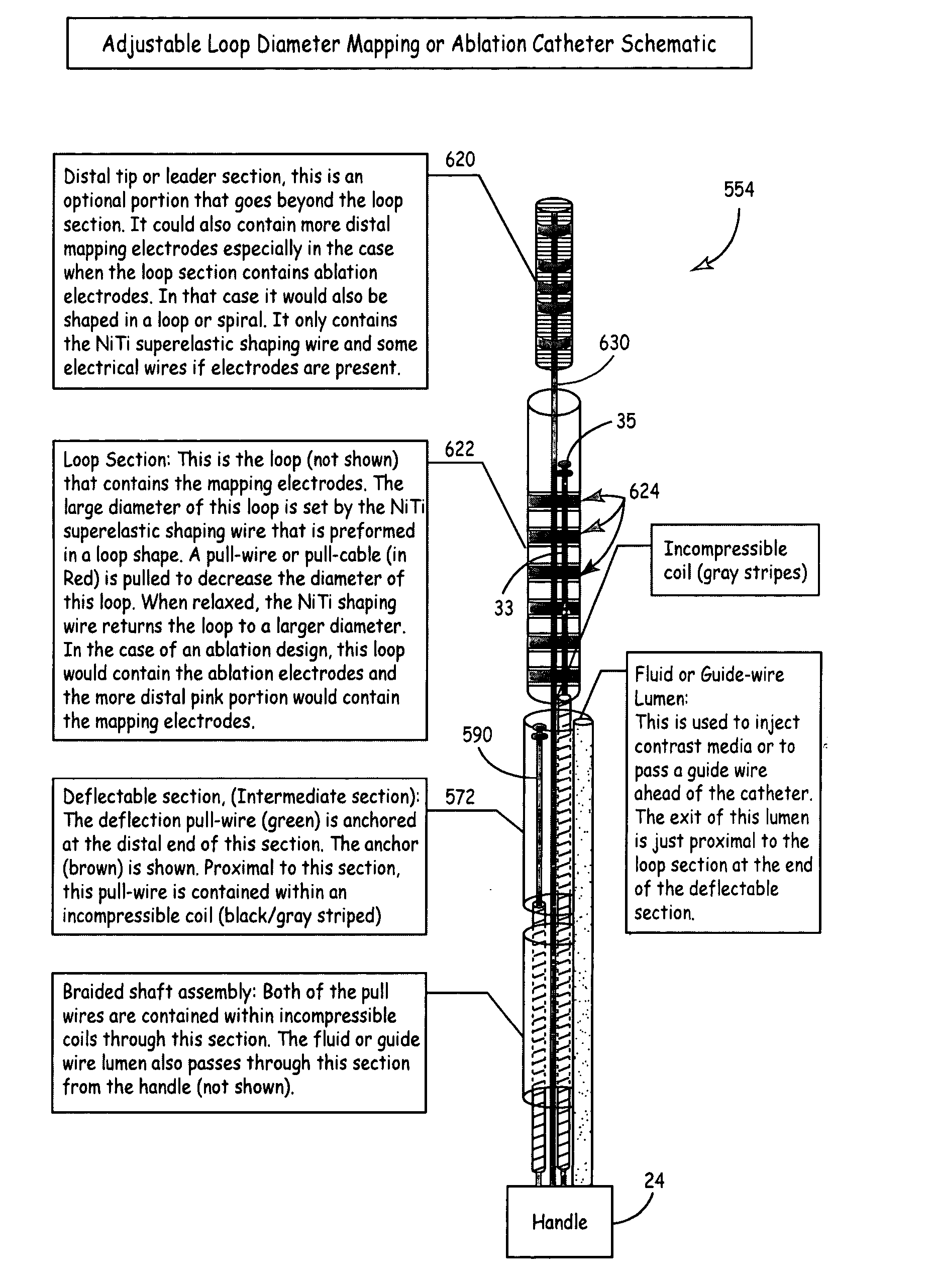
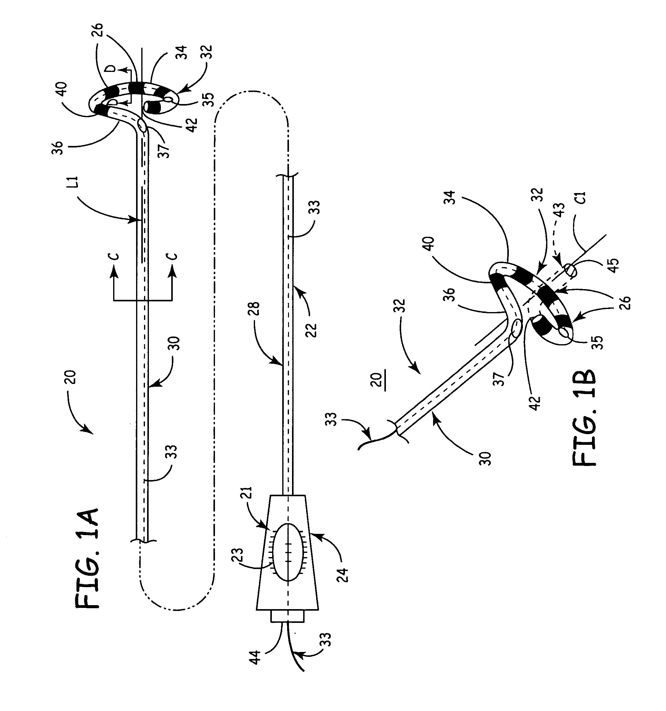
[0030] Either prior to or following deployment of a catheter according to the present invention, a clinician manipulates an elongated diameter-adjusting member (e.g., a pull wire, cable or the like) that couples to an anchoring mechanism disposed proximal the distal end of the loop portion or the decreasing diameter
helix—to adjust the diameter thereof. That is, when tension is applied to the pull wire or cable the diameter of the helix decreases and when compression is applied, particularly for embodiments having a elongated resilient member (e.g., a wire) slideably constrained within an elongated substantially resilient sheath the diameter of the
helical portion increases. Thus, a single catheter may be used for a variety of diameter PVO, MIs, vessels, etc. and said catheter may be advantageously manipulated to improve contact between the tissue and the distal portion of the catheter. While a single elongated member may be used to adjust the diameter of the
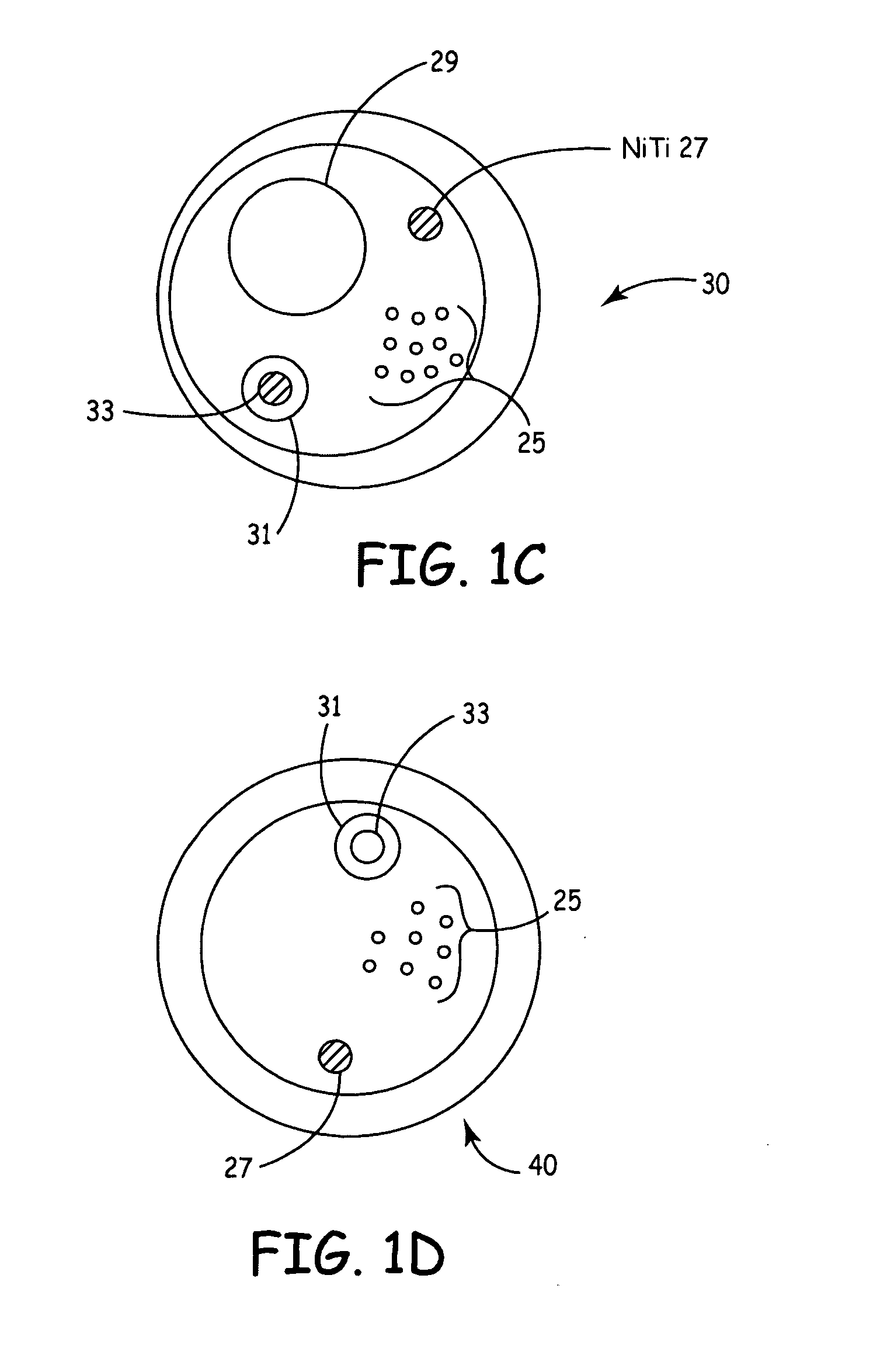
helical portion of the distal portion, a segment of a superelastic
shape memory alloy wire provides a substantially continuous diameter-
restoring force tending to increase the diameter of the loop or the helical portion. The super elastic shaping wire can be advantageously mechanically coupled inside the distal portion to the outer interior diameter thereof. The pull-wire (or cable) is disposed in a lubricious conduit (and / or the same lumen as the super elastic shaping wire). To reduce the diameter one simply manually applies tension to the pull-wire (or cable). In this embodiment, a shaping wire formed of nitinol (an
alloy of
nickel and
titanium that has the ability to return to a predetermined shape when heated).
[0031] As stated, the shaping wire can beneficially couple to the interior outer circumference of at least the majority of curvilinear portion of the helical portion. That is, the shaping wire is constrained inside an interior lumen of the helical portion on the wall portion of the lumen maximally spaced from the longitudinal axis of said loop or helical portion. Following fabrication a pull-wire of a catheter according to the present invention is subject to a slight amount of tension and heated to approximately 105 degrees Celsius for about two minutes. This process helps assure that the shaping wire and the pull-wire are situated on the proper side of the interior lumen within the distal portion (if sharing a common lumen). This process also efficiently and effectively helps the distal portion of the catheter assume and / or retain its arcuate (or curvilinear) shape.

