High resolution, dynamic positioning mechanism for specimen inspection and processing

a dynamic positioning and specimen technology, applied in the direction of motor/generator/converter stopper, dynamo-electric converter control, printer, etc., can solve the problems of increasing the risk of particulate contamination, complicated design of inspection/processing elements, and insufficient dynamic performance for many high-throughput applications, etc., to achieve high damping, avoid vibration, and reduce the effect of mass

Active Publication Date: 2005-01-20
NEWPORT CORP
View PDF3 Cites 27 Cited by
  • Summary
  • Abstract
  • Description
  • Claims
  • Application Information

AI Technical Summary

Benefits of technology

[0016] An advantage of the invention is that it also provides fine and dynamic theta positioning with fine adjustment capability, moderate travel range, high-bandwidth response, zero angular dither at any desired position, negligible influence on X-Y stage throughput, and angular rotation through the X-Y carriage rotational center.
[0017] A ZTT positioner of this invention employs a flexible disk that allows Z-axis displacement and tolerates tip and tilt rotations. The disk has minimum mass, stiffness in the X and Y directions, and high damping to avoid vibration. A driving system employs three non-contacting voice coil motors each having a spring to compensate for the moving mass. Position feedback is provided by non-contacting linear encoders coupled to each voice coil motor. The motors and encoders are mutually angularly spaced apart 120 degrees around the circumference of the disk to provide high sensitivity and accuracy.
[0018] The ZTT flexible disk includes multiple laminated plates. The upper plate is formed from a very stiff, low mass, ceramic material. The interface to the X-Y stage depends on the application, but could include a theta stage for angular alignment, a lift pin mechanism, and a wafer chuck. The ZTT positioner further includes adjustable hard limits to prevent contact between the wafer and the processing system.
[0019] Fine and dynamic theta positioners of this invention together provide fine adjustment capability, moderate travel range, high-bandwidth mechanical response, zero angular dither at the desired position, negligible influence on the X-Y stage throughput, and angular rotation through the center of the X-Y stage. The theta positioner is preferably integrated with the ZTT positioner.
[0020] The fine theta positioner employs an air bearing rotary stage with a centered pivot point to allow rotation through a few degrees. The air bearing rides on air pressure that is preloaded with a vacuum. After fine theta alignment, the pressure is shut off, thereby vacuum clamping the fine theta mechanism to a reference surface. The clamping provides a very stiff mechanism having minimum size and mass. The air bearing employs three air pads with an integrated interface for mounting the wafer chuck. The fine theta driving system employs a non-contacting voice coil motor. The angular feedback is provided by a non-contacting, high resolution angular encoder. During clamping, the motor and encoder are in a closed-loop configuration to ensure accurate angular positioning.
[0021] The dynamic theta positioner employs a flexible pivot driven by three piezo actuators spaced apart 120 degrees about a pivot point. The flexible parts are oriented to focus rotation about the pivot point, thereby avoiding parasitic X-Y displacements during angular rotation. The three flexible mechanisms each have a small size, but are mounted at a large radial distance from the pivot point to provide high ZXY stiffness even when loaded with several kilograms. The dynamic theta positioner is substantially frictionless and is clean and reliable.

Problems solved by technology

Moreover, ZTT devices should prevent contact between the wafer and the processing system, should not generate particles that could contaminate the wafer, and should be sufficiently reliable to maintain wafer processing throughput.
This approach complicates the design of the inspection / processing elements (typically a multi-element optical assembly) and increases the risk of particulate contamination because the vertical translation stage is typically located directly above the wafer.
Also, because the moving mass of the Z-axis translation stage (and the elements it carries) is greater than that of a wafer chuck, the resulting dynamic performance is inadequate for many high-throughput applications.
A problem with this approach is maintaining co-location of the inspection / processing system focal point and the tip and tilt positioner axes to prevent X-Y translation of the inspection / processing point as the tip and tilt angles are changed.
Of course, mass, complexity, and contamination risk remain problems with this over-wafer configuration.
This approach provides relatively large tip and tilt positioning angles but is problematic because it employs mechanical bearings and drive screws, has a high profile, and cannot directly measure the tip and tilt angles.
All these approaches are overly tall and massive to achieve suitable dynamic performance in high throughput applications.
This tradeoff limits either rotational range or stiffness.
This approach also suffers from limited range or a lack of mechanical stiffness.
However, the mass, height, and inherent mechanical properties of the bearing stage compromise the X-Y stage performance.
Moreover, achieving a desired zero-dither performance for the theta stage requires adding a brake or locking mechanism to the stage, which further increases the mass and complexity of the positioner.
However, because the stage is locked, it cannot provide the dynamic theta adjustments required by some applications.
Moreover, the travel range of this approach is limited by the rigid flexure mechanism and by a lateral shift that occurs between the actuator contact point.
Another disadvantage of this approach is that the center of rotation is offset from the X-Y carriage center, making it necessary to compensate in X-Y for the theta offset angle.
While this solution adds little hardware to the X-Y system to provide theta functionality, it still has a limited travel range and provides no way to lock the theta position.

Method used


Image

  • High resolution, dynamic positioning mechanism for specimen inspection and processing
  • High resolution, dynamic positioning mechanism for specimen inspection and processing
  • High resolution, dynamic positioning mechanism for specimen inspection and processing

Examples


Embodiment Construction

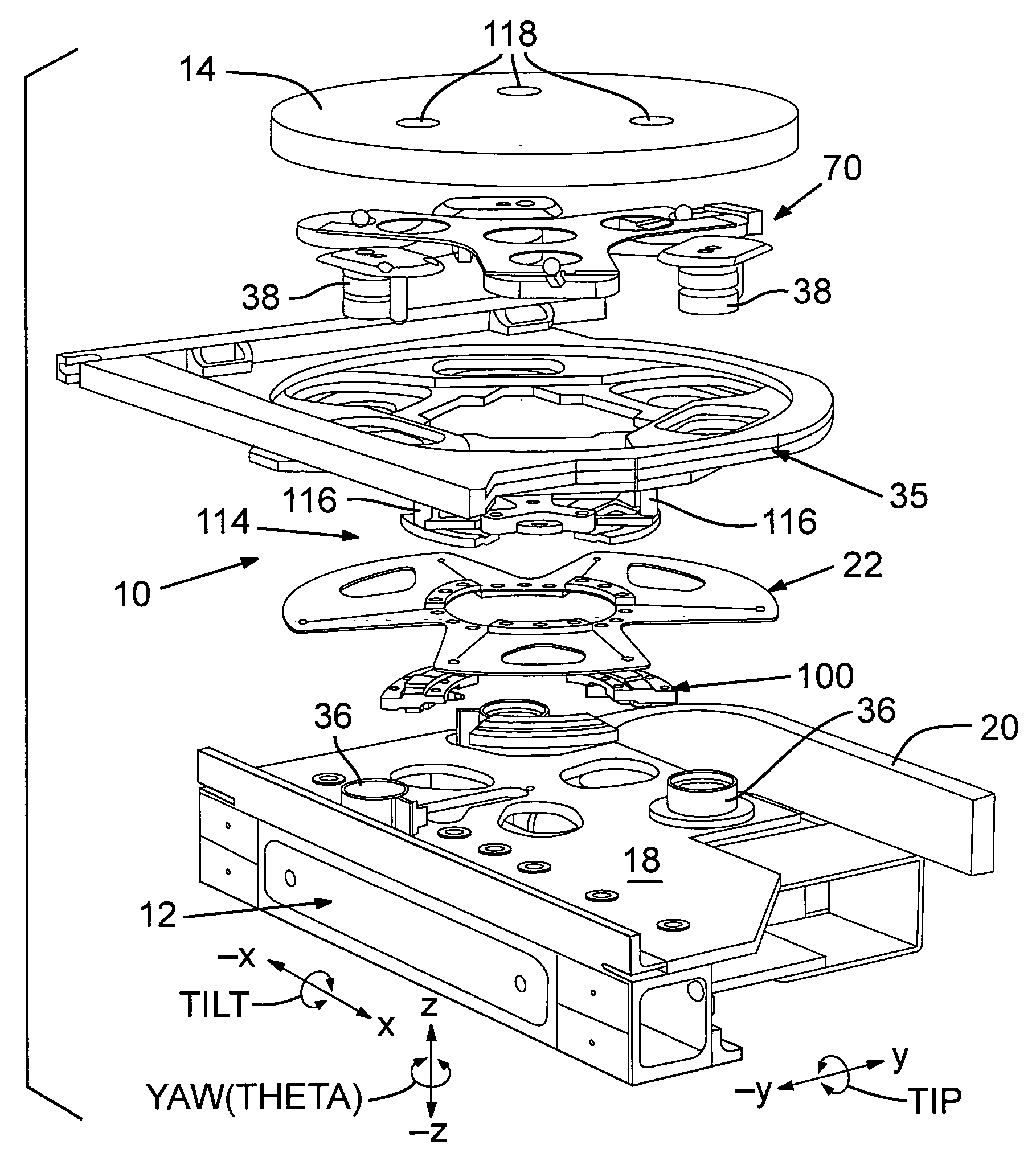
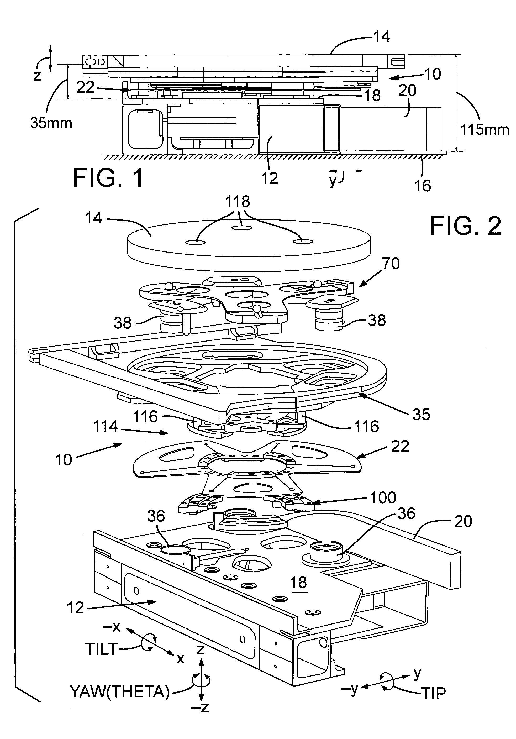
[0030]FIGS. 1 and 2 show respective side elevation and exploded views of a preferred embodiment of a ZTT-Theta positioner 10, which is assembled between the top of an X-Y stage 12 and the bottom of a wafer mounting chuck 14. X-Y stage 12 moves in X- and Y-axis directions relative to a flat surface 16, such as a granite slab. ZTT-Theta positioner 10 is mounted to an upper surface 18 of X-Y stage 12 and acts to accurately move chuck 14 in the Z-axis direction, tip (roll) chuck 14 about the X-axis, tilt (pitch) chuck 14 about the Y-axis, and rotate (yaw) chuck 14 about the Z-axis. Accordingly, chuck 14 undergoes six-axes of controlled movement in the X, Y, Z, roll, pitch, and yaw directions.

[0031] ZTT-Theta positioner 10 is a low-profile assembly occupying only about 35 mm of the total 115 mm height of X-Y stage 12, positioner 10, and chuck 14. X-Y stage 12 is electrically connected to a controller (not shown) by a flexible cable 20. The low-profile reduces angular torque by keeping t...


PUM

PropertyMeasurementUnit
heightaaaaaaaaaa
heightaaaaaaaaaa
distancesaaaaaaaaaa

Abstract

A specimen positioning mechanism (10) includes a movable stage (12) movable along multiple axes, a plate (35) connected to and supporting a specimen mounting chuck (14), multiple linear displacement mechanisms (36, 38) coupling the plate to the movable stage and mutually spaced apart at different locations between the movable stage and the plate and separately controllable to change distances between the movable stage and the plate, and a flexible member (22) coupling the movable stage and the plate. The flexible member is motion compliant in three axes of motion. The flexible member in response to linear displacements of the linear displacement mechanisms allows linear and rotational movement of the specimen mounting chuck in the three axes of motion compliance.

Description

RELATED APPLICATION [0001] This application claims benefit of U.S. Provisional Application No. 60 / 488,141, filed Jul. 17, 2003.TECHNICAL FIELD [0002] This invention relates to the field of semiconductor processing devices and, more particularly, to a system for dynamically aligning a wafer in Z-, tip-, tilt-, and yaw-(theta) axes relative to a wafer processing device. BACKGROUND INFORMATION [0003] There are various prior Z Tip Tilt (“ZTT”) devices for adjusting the height and parallelism of a semiconductor wafer in a semiconductor processing machine. ZTT devices typically control positioning of Z-axis displacement, rotation about an X-axis, and rotation about a Y-axis while the semiconductor wafer is moving in the X-Y directions under a semiconductor processing machine, such as an optical inspection system. The ZTT device dynamically compensates for non-flatness of the wafer and should be stiff to provide high bandwidth positioning. [0004] Typical ZTT devices are mounted on an X-Y p...

Claims


Application Information

Patent Timeline
Patent Type & Authority Applications(United States)
IPC IPC(8): B25B5/08G01B11/00G03B27/42G03B27/58G03F7/20H01LH02K41/00
CPCG03B27/58G03F7/70758G03F7/70716G03F7/707
Inventor JEANNE, ALAINDURAND, ERICDESAILLY, ROGER
Owner NEWPORT CORP
Why Eureka
Try Eureka