Preferential precipitation membrane system and method

a precipitation membrane and precipitation technology, applied in the field of water treatment, can solve the problems of inefficiency of operation at reduced recovery rate, inability to control the precipitation of mineral compounds (scale) on the membrane surface, and limited purity of the feed stream, so as to achieve high recovery rate, high saline feed water recovery rate, and high tds rejection rate

Inactive Publication Date: 2005-01-27
ITT MFG ENTERPRISES LLC
View PDF21 Cites 35 Cited by
  • Summary
  • Abstract
  • Description
  • Claims
  • Application Information

AI Technical Summary

Benefits of technology

[0005] The present invention is directed to a system and method for removing solutes from an aqueous solution containing a high level of sparingly soluble inorganic solutes (for example, but not limited to, a waste water stream) in a manner that achieves a high recovery rate of the water content of the solution, as well as a high removal rate of the solutes contained in the solution in an efficient, continuous flow membrane process. The invention is particularly useful for producing product water with less than 500 mg / L of total dissolved solids (TDS) from initial feed streams containing between 3,000 and 20,000 mg / L of TDS with high levels of non-carbonate hardness (e.g., 1,000 to 2,500 mg / L of calcium and magnesium hardness expressed as calcium carbonate equivalents).
[0007] As an additional part of the present desalination system and method, a means is provided to separate the retentate stream from the first-pass NF membrane process into (i) a discharge stream containing a minority of the nucleation crystals and water content of the NF retentate, and (ii) a recycle stream containing a majority of the nucleation crystals and water content of the NF retentate. Before the discharge stream is discharged from the system, it may be further separated using a settling tank, hydrocyclone, or any other suitable solids / liquid separation device into (i) a fraction containing a higher level of suspended solids and (ii) a fraction containing a lower level of suspended solids. Different fractions of these separate streams may be discharged from the system to control independently the amount of dissolved solids and the amount of suspended solids that are returned to, or discharged from, the system. The recycle stream containing a majority of the nucleation crystals and water content of NF retentate stream is returned to the feed-side of the NF unit in a preferred embodiment. This configuration enables the majority of nucleation crystals to be reused in the process so that it is possible after startup to operate the system on a continuous basis without having to add nucleation crystals. Finally, in a preferred embodiment, a retentate stream from the second-pass RO unit is also recycled, at least in part, to the feed stream of the NF unit.
[0008] By providing and operating a double-pass membrane system in the manner described above, it is possible to recover high levels of high-hardness saline feed water as low salinity product water (<500 mg / L TDS) without fouling the membrane elements and without having to add scale inhibitors. The present invention also allows the simultaneous achievement of higher recovery rates and higher TDS rejection rates than would be possible in a single-pass design.

Problems solved by technology

In conventional membrane desalination methods, the purity of the feed stream is usually limited by one or more sparingly soluble constituents in the feed stream, or by the inability of the soluble or sparingly soluble constituents to stay in solution as the concentration of the sparingly soluble constituents increases on the high pressure side of the membrane.
In prior processes, the precipitation of mineral compounds (scale) on the membrane surface could not be controlled, except by the addition of antiscalants or by inefficient operation at reduced recovery rates (e.g., constant repetitive shut-downs for cleaning, etc.).

Method used


Image

  • Preferential precipitation membrane system and method
  • Preferential precipitation membrane system and method
  • Preferential precipitation membrane system and method

Examples


Embodiment Construction

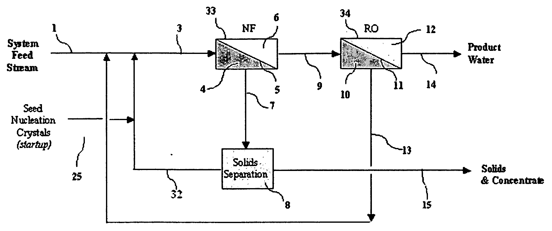
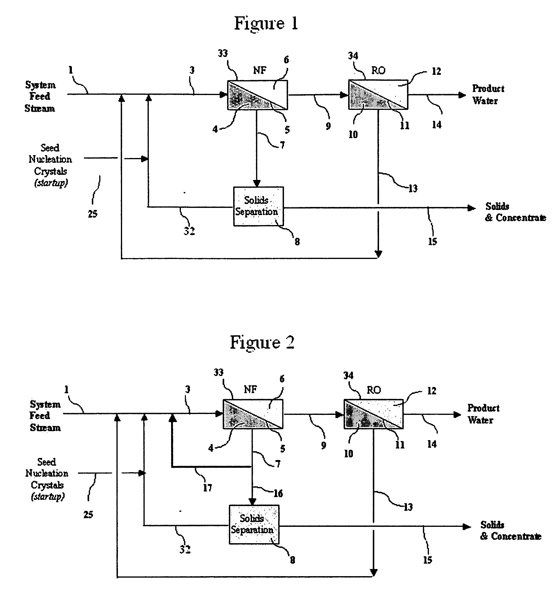
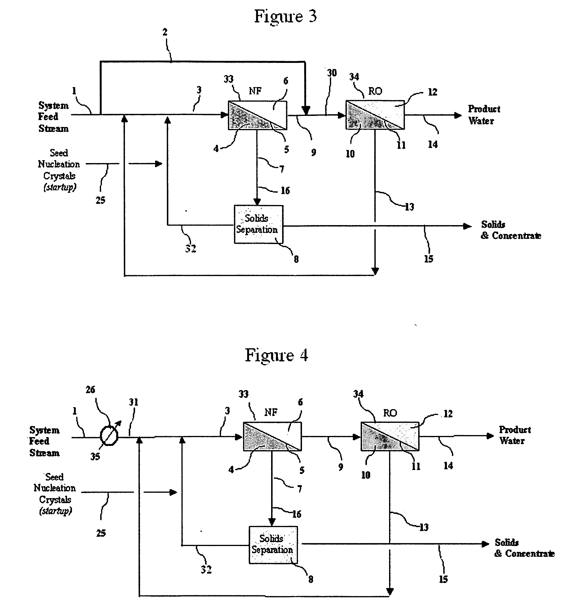
[0016] One embodiment of the present invention in which two membrane separation units are connected is shown in FIG. 1. In FIG. 1, first-pass membrane separation unit 33 is designated as a nanofiltration (NF) membrane, and second-pass membrane separation unit 34 is designated as a reverse osmosis (RO) unit. The use of these terms is not restrictive. The precise type of membrane used in each pass may vary depending on the application and desired performance of the system. For example, the first-pass membrane separation unit may be a multiple stage semi-permeable membrane barrier device.

[0017] In this embodiment, liquid feed stream 1 to be purified, e.g., hard water containing silica, calcium carbonate, calcium sulfate and suspended solids or wastewater or groundwater containing the same, is combined (i) with majority fraction stream 32 from the solids separation unit 8 containing a controlled amount of the nucleation crystals being returned to the process and (ii) with the retentate...


PUM

PropertyMeasurementUnit
temperatureaaaaaaaaaa
pHaaaaaaaaaa

Abstract

A system and method for desalinating a feed solution containing a high level of sparingly soluble solutes, such as calcium sulfate, in which a high percentage of the water content of the feed solution is recovered as purified water. The method and system comprise introducing a sufficient quantity of nucleation crystals on the low pressure side of a first-pass membrane separation unit so that the sparingly soluble solutes precipitate on the suspended nucleation crystals, instead of on the surface of the first-pass semi-permeable membrane barrier. The permeate from the first-pass membrane separation unit is then sent to the high pressure side of a second-pass membrane separation unit. The second-pass semi-permeable membrane barrier rejects additional dissolved solutes, some of which can be recycled back to the first-pass membrane, so that permeate with a low level of dissolved solutes is produced on the low pressure side of the second-pass membrane barrier.

Description

[0001] This application claims priority of U.S. Provisional Patent Application Ser. No. 60 / 457,074 filed Mar. 24, 2003.FIELD OF INVENTION [0002] The present invention relates to water treatment and, more specifically, to a method and system of removing solutes from an aqueous solution containing a high level of sparingly soluble inorganic solutes. BACKGROUND OF THE INVENTION [0003] In conventional membrane desalination methods, the purity of the feed stream is usually limited by one or more sparingly soluble constituents in the feed stream, or by the inability of the soluble or sparingly soluble constituents to stay in solution as the concentration of the sparingly soluble constituents increases on the high pressure side of the membrane. A fraction of the soluble or sparingly soluble constituents eventually precipitates out during the membrane separation process, resulting in a decrease in liquid that permeates the membrane. [0004] To overcome this problem, chemicals referred to as ...

Claims


Application Information

Patent Timeline
Patent Type & Authority Applications(United States)
IPC IPC(8): B01D61/02B01D61/04C02F1/44
CPCC02F1/441B01D61/022Y02W10/37Y02A20/131B01D61/026B01D61/029
Inventor ENZWEILER, RONALD J.ALLAN, PETERSTRASSER, JURGEN HEINZ
Owner ITT MFG ENTERPRISES LLC
Why Eureka
Try Eureka