Fuel tank resistor card having improved corrosion resistance

a fuel tank and resistor card technology, applied in the field of variable resistors, can solve the problems of assembly being exposed to severe vibration, voltage change, assembly having to go through thousands of cycles in a harsh environment, etc., and achieve the effect of improving corrosion resistance and wear resistan

Inactive Publication Date: 2005-02-24
CTS CORP ELKHART
View PDF5 Cites 16 Cited by
  • Summary
  • Abstract
  • Description
  • Claims
  • Application Information

AI Technical Summary

Benefits of technology

[0012] It is a feature of the present invention to provide a resistor card for a fuel level sensor that has improved resistance to corrosion and wear.
[0013] It is a feature of the present invention to provide a resistor card for a fuel level indicator system. The resistor card has a substrate that has a first and a second surface. A resistive layer is disposed on the first surface. A conductive layer is disposed on the first surface. A nickel layer covers the conductive layer. An alloy layer covers the nickel layer. The alloy layer protects the conductive layer from corrosion.
[0014] Another feature of the present invention is to provide a resistor card for a fuel sensor. The resistor card has a ceramic substrate with a first and second surface. A resistive path is located on the first surface. A conductive path is located on the first surface. A barrier layer is located over the conductive path. The barrier layer seals the conductive path from corrosion. An electroplated alloy layer is located over the barrier layer. The alloy layer provides a long lasting wear surface.

Problems solved by technology

This results in a voltage change that generates a signal representative of the amount of fuel contained in the tank.
One problem with this type of system is that over the life of a vehicle the assembly must go through thousands of cycles in a harsh environment.
In addition, the assembly is exposed to severe vibration resulting from vehicle movement.
The electrical resistance of the metalization portions may increase and cause accuracy problems with the fuel reading.
Additionally, the metalized portions may wear to the point that an open circuit is created on the card.
Unfortunately, silver is also chemically reactive to compounds found in fuels.
Unfortunately, the cost of gold, palladium and platinum is about 100 times greater than the cost of silver.
This results in a resistor card that is prohibitively expensive.

Method used


Image

  • Fuel tank resistor card having improved corrosion resistance
  • Fuel tank resistor card having improved corrosion resistance
  • Fuel tank resistor card having improved corrosion resistance

Examples


example 1

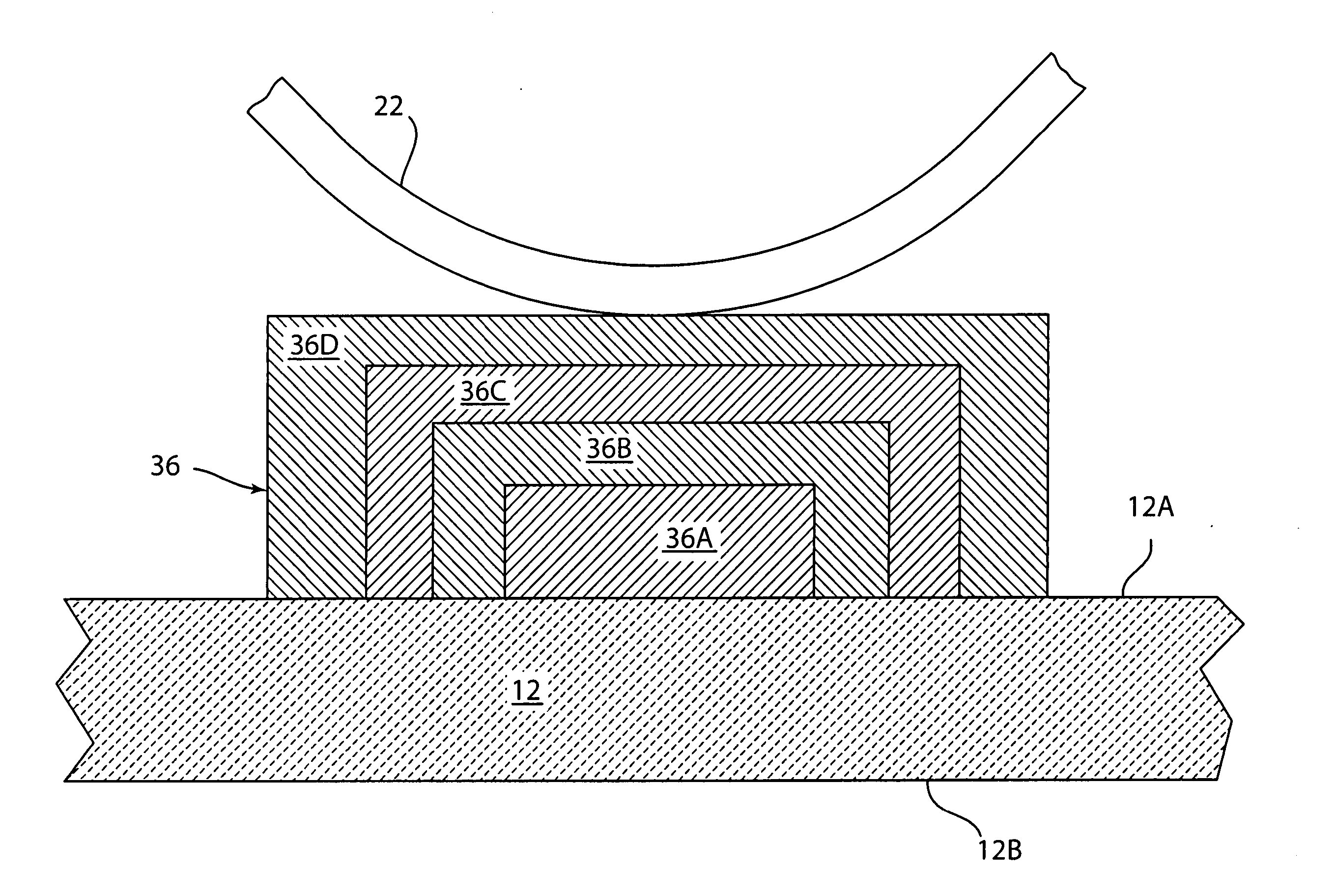
[0029] A resistor card was fabricated according to the present invention. An aluminum oxide substrate was used. Layers 36A, 36B, 36C and 36D were formed from the following materials:

Conductive layer 36A97.0 wt. % silver / 1.0 wt. %wt. % glass.platinum / 2.0First nickel strike layer 36B100 wt. % nickel.Second electroless nickel layer 36C100 wt. % nickel.Alloy layer 36D1.0 wt. % nickel / 99.0 wt. % gold

[0030] The resistor card of example 1 was tested for several performance parameters. The card was mated with a palladium alloy wiper and dry cycled for 1 million cycles. Visual inspection of the wear surfaces on the gold alloy showed very little wear of the alloy layer and none of the underlying nickel layer was exposed. The card was tested for noise performance. Noise performance was tested by cycling the wiper with a 5 volt applied voltage while measuring the output voltage. The resistor card of example 1 showed no noise spikes greater than 0.15 Volts after 1 million cycles. In comparison...


PUM

PropertyMeasurementUnit
output voltageaaaaaaaaaa
resistive areaaaaaaaaaaa
conductiveaaaaaaaaaa

Abstract

A resistor card for a fuel level sensor has improved resistance to corrosion and wear. The resistor card has a substrate with a resistive layer and a conductive layer. A nickel layer covers the conductive layer. A nickel-gold alloy layer covers the nickel layer. The nickel-gold alloy layer protects the conductive layer from sulfur corrosion and improves wear resistance.

Description

CROSS REFERENCE TO RELATED AND CO-PENDING APPLICATIONS [0001] The present application is a division of U.S. patent application Ser. No. 10 / 406,356, filed on Apr. 3, 2003 and entitled, “Fuel Tank Resistor Card Having Improved Corrosion Resistance”. The contents of which are herein incorporated by reference in entirety.BACKGROUND OF THE INVENTION [0002] 1. Field of the Invention [0003] The present invention relates to variable resistors and in particular to a ceramic resistor card for use in a fuel level sensor that is lower in cost and has improved resistance to sulfur corrosion. 2. Description of the Related Art [0004] Variable resistors are known for sensing parameters in a variety of applications. For example, the fuel level in an automobile tank is typically measured using a variable resistor having a sweep arm mechanically or electrically coupled to a float located in a fuel tank. The sweep arm position varies according to the float level. The position of the sweep arm can be de...

Claims


Application Information

Patent Timeline
Patent Type & Authority Applications(United States)
IPC IPC(8): G01F23/36H01C10/30H01C17/065H05K1/09H05K1/16H05K3/24
CPCG01F23/36H01C10/305H01C17/06526H05K2201/0347H05K1/167H05K3/246H05K1/092
Inventor DEDERT, RONALDHEIMANN, ROBERTHOFFMAN, CRAIGKURTZ, KEVIN
Owner CTS CORP ELKHART
Why Eureka
Try Eureka