Method of producing solid wire for welding

a solid wire and welding technology, applied in the direction of soldering apparatus, drawing dies, manufacturing tools, etc., can solve the problems of high feedability degradation, easy scraping of excess lubricant, drawbacks of solid wire for welding with copper plating or lubricant coating, etc., and achieve high-efficiency welding solid wire

Active Publication Date: 2005-03-03
KOBE STEEL LTD
View PDF7 Cites 40 Cited by
  • Summary
  • Abstract
  • Description
  • Claims
  • Application Information

AI Technical Summary

Benefits of technology

According to a preferred embodiment of the present invention, a step of drawing by means of hole dies may be performed, before or between a series of drawing by means of roller dies, in such a way that the total reduction of diameter ΣRd is in the range of 0.5% to 78%. The advantage of this embodiment is that it is possible to uniformly apply a lubricant to the surface of the wire which has been drawn by means of hole dies, so that drawing in the subsequent step by means of roller dies can be accomplished without a new dry solid lubricant being applied for drawing.
The present invention provides a method for producing highly efficiently welding solid wires free of copper plating by a continuous in-line process which includes drawing from a steel stock wire to a finished or nearly finished wire by means of roller dies, washing of drawing lubricants, and application of feeding lubricants. The method of the present invention may be applicable to high-speed drawing of not only mild steel solid wires for welding which do not have copper plating but also high-strength steel wires for welding which do not have copper plating. (High-strength steel includes high-tensile steel, alloy steel, stainless steel, etc.)

Problems solved by technology

This feed resistance is not so large in a straight conduit liner as to pose problems with feedability.
However, in the case of a long conduit liner or a sharply or repeatedly bent conduit liner, the feed resistance increases to such an extent that it does not balance with the feeding force any longer, resulting in the feedability deteriorating extremely.
Unfortunately, a solid wire for welding with copper plating or lubricant coating has drawbacks.
That is, excess lubricant is easily scraped off as the solid wire is pressed by the feed roller.
Residues of scraped lubricant enter the conduit liner and accumulate therein, which leads to an anomalous increase in feed resistance.
Copper plating also causes a similar trouble.
Residues scraped off from the copper plating pose a serious problem with an extreme increase in feed resistance.
Moreover, the cyan compound used for copper plating is a source of environmental pollution.
Such surface treatment poses problems with production cost and environmental pollution.
Unfortunately, since calcium produces an extremely adverse effect on arc stability, calcium soap has to be removed by annealing, alkali degreasing, pickling, and washing with an organic detergent after drawing (to the final diameter or intermediate diameter).
This also poses problems with production cost and environmental pollution.
On the other hand, a solid wire for CO2 gas shield arc welding suffers difficulties in firmly holding a predetermined amount of lubricating oil if it has a compact smooth surface.
The foregoing technologies, however, are not practicable for a solid wire for welding which has no copper plating.
In other words, they are incapable of providing the wire surface with irregularities large enough for them to hold sufficient lubricating oil, while maintaining the efficient wire productivity.
The disadvantage of a solid wire for welding which has no copper plating is its incapability of high-speed drawing through a hole die for the following reason.
This problem readily arises when hole die drawing is carried out without the wire being treated with a lubricant of calcium stearate.
The same problem as above is also involved in the above-mentioned two-stage drawing process, which consists of dry hole die drawing and wet drawing.
This drawing process is not applicable to high-speed drawing of a wire without copper plating because wet drawing is inferior to dry drawing in drawability.
Moreover, as described in U.S. Pat. No. 6,079,243-given above, the surface roughness of a wire rapidly decreases during drawing, and hence it is difficult for the wire to maintain its surface roughness throughout the drawing process from the semi-finished stage (in which surface irregularities are made) to the final stage.
The above-mentioned MoS2 and WS2 as the drawing lubricant do not provide sufficient drawability in hole die drawing and roller die drawing, which makes it difficult to perform high-speed drawing on a wire without copper plating.
Moreover, such lubricants remaining in excess amounts make unstable electric current flowing through the finished wire and residues of scraped lubricants aggravate the wire feedability.
These problems lead to inefficient drawing and unstable quality.
In addition, direct application of sulfides (such as MoS2 and WS2), without adequate rust-preventive treatment on the stock wire, deteriorates the corrosion resistance of welding wire.
The disadvantage of transferring surface irregularities to the wire surface from a roller die is that it is very difficult to control the roller surface which is subject to wear.
This leads to unstable wire quality and high production cost due to frequent roller replacement.
However, the roller die has never been used to draw a welding solid wire free of copper plating at a high speed from the stock to the finished product.
Drawing a welding solid wire free of copper plating without adverse effects on welding performance is limited in speed so long as it relies only on roller dies.
High-speed drawing with roller dies presents more difficulties in the case of high-strength steel welding wire free of copper plating than in the case of ordinary mild steel welding wire.
As compared with mild steel welding wires, high-strength steel welding wires need a larger drawing force and hence exerts a larger load on the roller dies.
With a large working force applied during drawing, the roller dies are subject to deformation and vibration, because the roller dies and their supporting frames are limited in strength and stiffness.
This vibration causes the welding wire to come into contact with the roller die intermittently, thereby leaving minute dents on the wire surface.
Such dents aggravate the accuracy of wire diameter and lead to the surface roughening of the wire.
This leads to a low drawing efficiency and a low wire productivity.
Even though such an instance exists, it would be impossible to draw a high-strength welding solid wire at a high speed.
The limitation of drawing speed is attributable to the roller dies which wear out and pose a problem with lubrication (as in the hole die).
Unfortunately, calcium soap remaining on the surface of the finished welding wire, however small the amount may be, greatly aggravates the arc stability.
The result is high production cost and environmental pollution.
Therefore, the use of calcium soap is detrimental to production of a welding wire free of copper plating.
Even though such a process exists, it would be impossible to carry out these steps at the same high speed as drawing.
Moreover, welding wires have never been produced by a continuous process including drawing, washing to remove drawing lubricants, and application of feeding lubricants.
Even though such a continuous process exists, it would have been impossible to run it at a high speed.

Method used


Image

  • Method of producing solid wire for welding
  • Method of producing solid wire for welding
  • Method of producing solid wire for welding

Examples


example 1

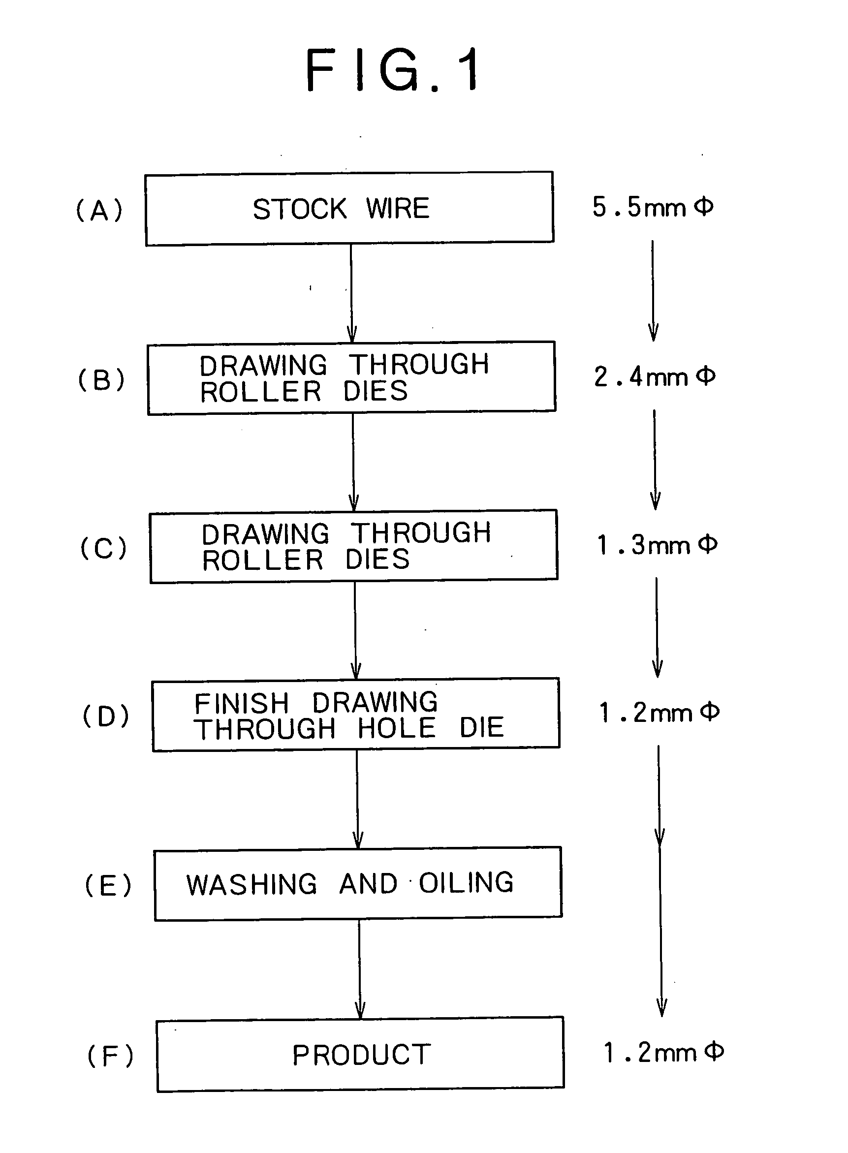
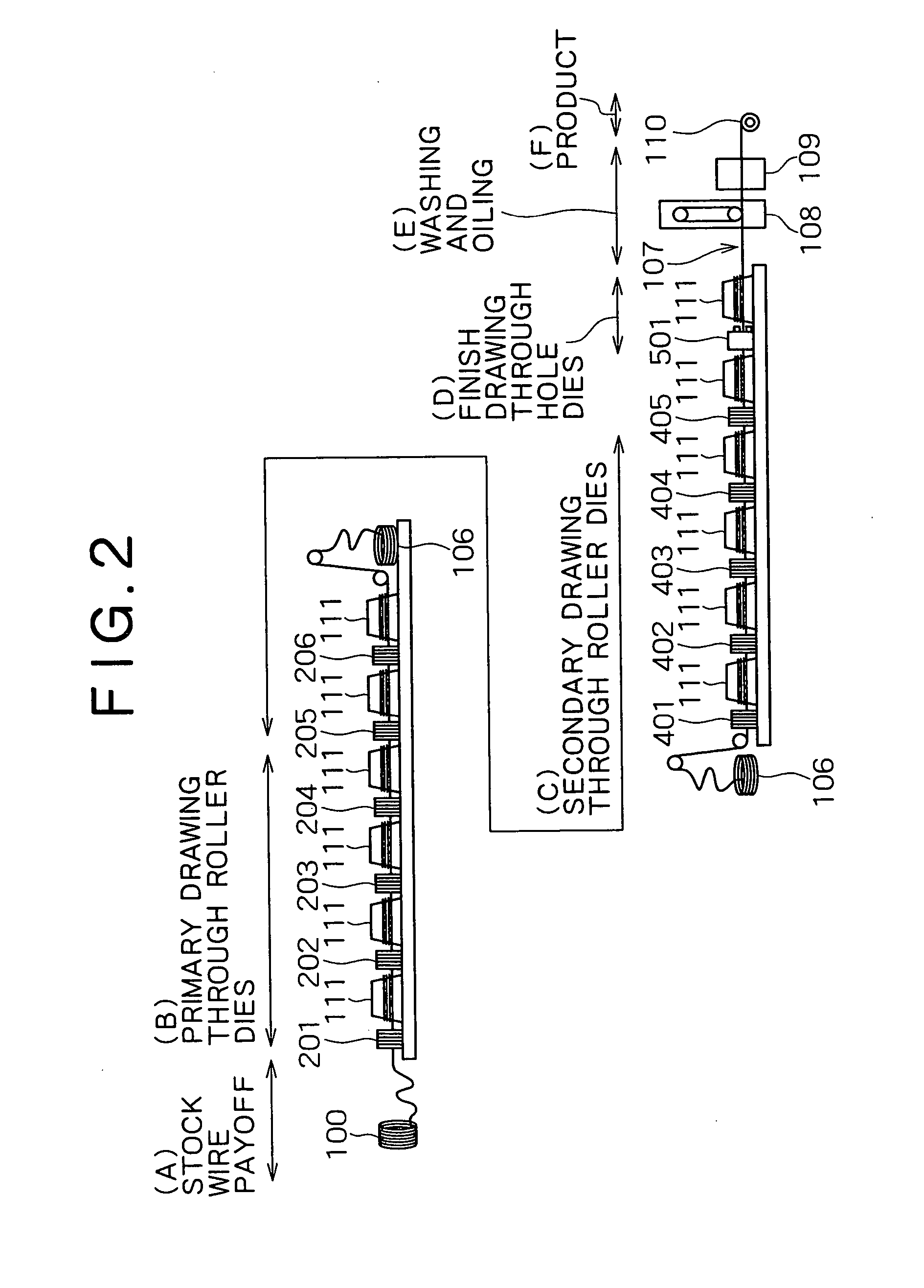
This example demonstrates the production of a welding solid wire by the process shown in FIG. 2. This process consists of the primary drawing step (B) and the secondary drawing step (C), both by means of roller dies. The two drawing steps made a high-strength stock wire (5.5 mm in diameter) into a welding wire (1.2 mm in diameter). Before the primary drawing step (B), the stock wire was coated with a dry solid lubricant for drawing. Before the secondary drawing step (C), the half drawn wire was also coated with a dry solid lubricant for drawing. Incidentally, this example did not include the step of finish drawing by means of the hole die 501 (shown in FIG. 2) after drawing.

The drawn wire (which has the diameter of the product wire) underwent the washing step (E) by means of a simple washing bath 108 containing no organic detergent, acid or alkali, so that the wire surface was cleaned of residual lubricant for drawing. In the subsequent oiling step (E), the washed wire was coated...

example 2

Samples of welding solid wires (free of copper plating), 1.2 mm in diameter, were prepared from high-strength stock wires, 5.5-2.4 mm in diameter, under the same conditions as in Example 1, except that hole dies were placed in the first drawing step (B) for continuous drawing such that Rd was 50.7% (sum of reduction in diameter). The stock wire was coated with a dry solid lubricant before the primary drawing step (B) with hole dies. The half drawn wire was not coated again with the dry solid lubricant in the secondary drawing step (C) with roller dies. In other words, drawing in the secondary drawing step (C) was accomplished with the help of residual lubricant only. The primary drawing step (B) relies on four hole dies of WC—Co cemented carbide arranged in series and three roller dies arranged in series thereafter.

The stock wires were drawn by means of the hole dies under the same condition. The effect of the drawing lubricant (which varies in composition) on drawability in the ...


PUM

PropertyMeasurementUnit
distanceaaaaaaaaaa
distanceaaaaaaaaaa
diameteraaaaaaaaaa

Abstract

A method for efficient production of a welding solid wire free of copper plating. The method consists of drawing by means of roller dies with the help of a dry solid lubricant for drawing which is at least either of sodium stearate or potassium stearate, removing the lubricant from the wire surface by means of a washing device, and applying a lubricant for wire feeding to the surface of the drawn wire by means of an oiling device. High-speed drawing by means of roller dies makes a stock wire into a welding solid wire having the diameter of the finished wire or nearly finished wire. The drawing step is followed by the washing step and the lubricant applying step, which are all accomplished in-line.

Description

BACKGROUND OF THE INVENTION 1. Field of the Invention The present invention relates to a method of producing a solid wire for welding which has no copper plating. (In this specification, a simple term “wire” may be used in place of “solid wire”.) 2. Description of the Related Art It is common practice to use a thin solid wire for welding (0.8-1.6 mm in diameter) in CO2 gas shield arc welding and MIG welding. When in use, the solid wire for welding is wound on a spool or placed in a pail pack. It is pulled out of the spool (or pail pack) by a feed roller and then pushed into a liner enclosed by a conduit cable and finally sent through the liner to the nozzle of the welding torch at the welding position. The conduit liner mentioned above is a flexible guide tube formed from a spirally wound steel wire. It is usually 3-6 meters long and sometimes as long as 10-20 meters, depending on the distance to the welding position. The feeding of a wire for welding should be accomplished sta...

Claims


Application Information

Patent Timeline
Patent Type & Authority Applications(United States)
IPC IPC(8): B21C1/02B21C3/08B21C9/00B21C43/02B23K35/02B23K35/40
CPCB21C1/02B23K35/40B21C43/02B21C9/005
Inventor KONISHI, YOSHIHIROSHIMIZU, HIROYUKIYOKOTA, YASUYUKI
Owner KOBE STEEL LTD
Why Eureka
Try Eureka