

System, method and apparatus for improved electrical-to-optical transmitters disposed within printed circuit boards
a technology of printed circuit board and electrical-to-optical transmitter, which is applied in the field of optoelectronic systems, can solve the problems of difficult realization of effective heat dissipation, and achieve the effect of simple and reliable fabrication process
- Summary
- Abstract
- Description
- Claims
- Application Information
AI Technical Summary
Benefits of technology
Problems solved by technology
Method used
Image

Examples
Embodiment Construction
While the making and using of various embodiments of the present invention are discussed in detail below, it should be appreciated that the present invention provides many applicable inventive concepts that can be embodied in a wide variety of specific contexts. The specific embodiments discussed herein are merely illustrative of specific ways to make and use the invention and do not delimit the scope of the invention.
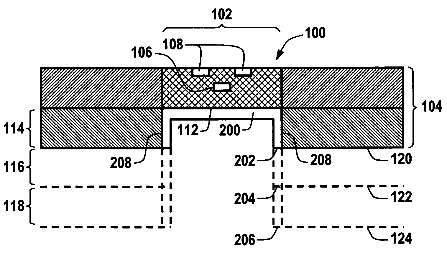
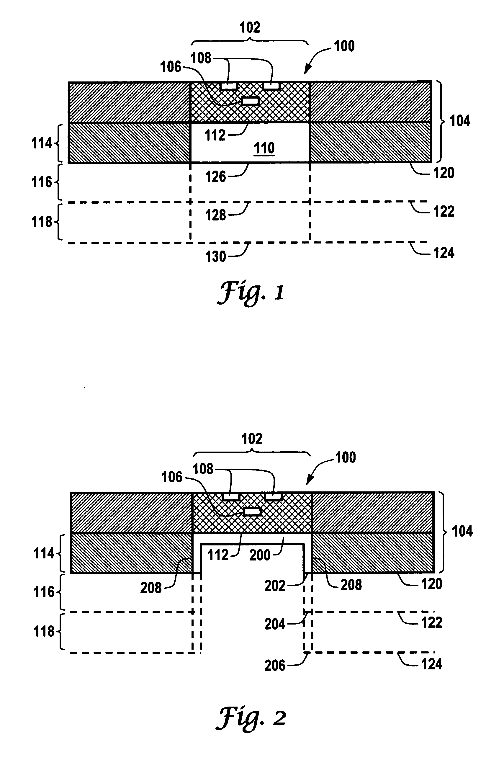
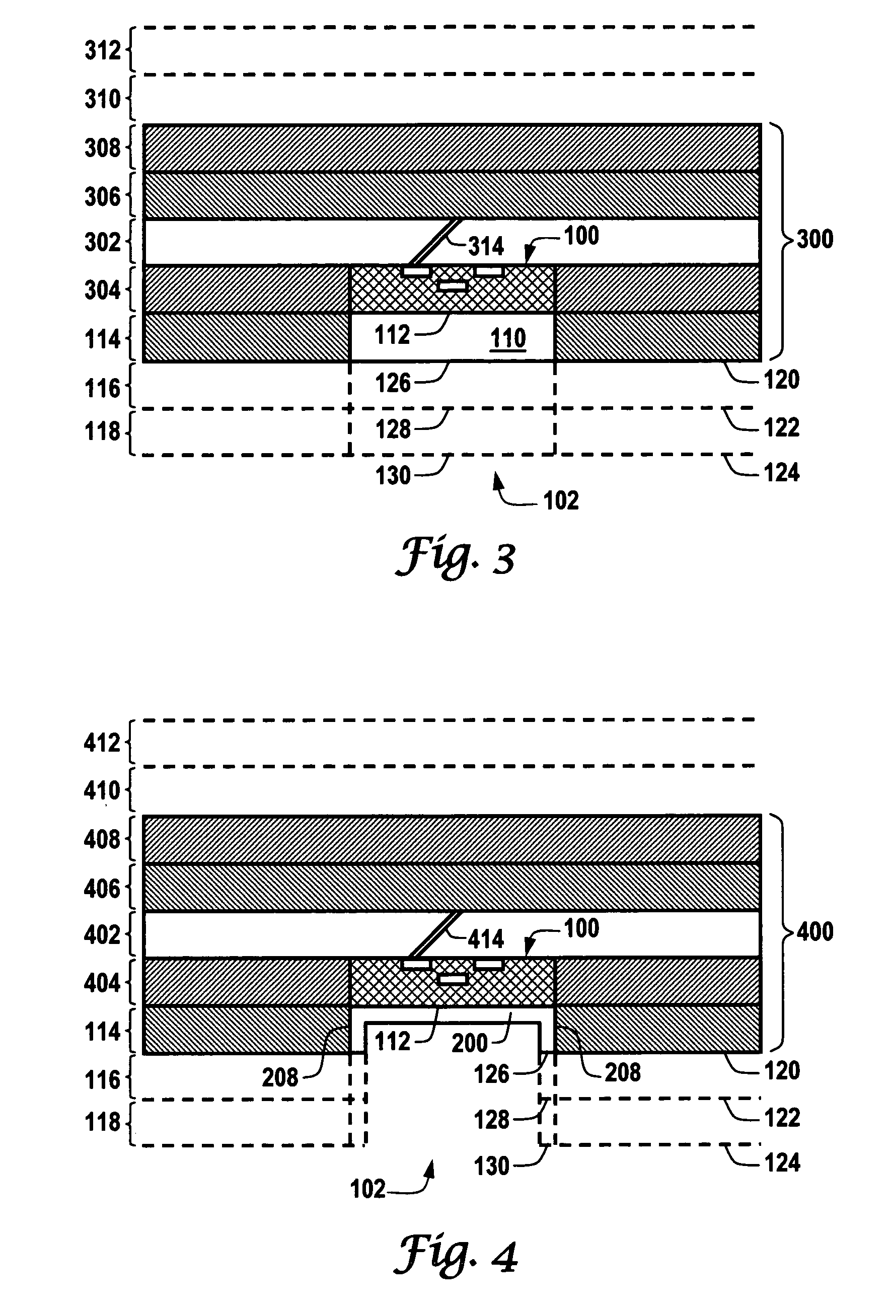
The present invention uses inventive heat dissipation and fabrication techniques to improve electrical-to-optical transmitters disposed within a printed circuit board. First, the present invention provides an effective heat sink embedded within the electro-optical hybrid printed circuit board using a simple and reliable fabrication process that does not require additional steps. Second, the present invention provides an improved method to fabricate the reflective element disposed within the channel waveguide structure. Third, the present invention provides an improv...
PUM
 Abstract
Description
Claims
Application Information