Wireless device isolation in a controlled RF test environment

Inactive Publication Date: 2005-03-10
AZIMUTH NETWORKS
View PDF31 Cites 140 Cited by
  • Summary
  • Abstract
  • Description
  • Claims
  • Application Information

AI Technical Summary

Benefits of technology

[0022] Another feature of the present invention is directed towards the printed circuit board, that helps attenuate undesired RF signals on a plurality of electrical signal paths, for example on a PCI bus. The printed circuit board includes a plurality of signal paths, wherein each signal path passes through a first filtering component, the first filtering component positioned within a first

Problems solved by technology

However, unlike with the Ethernet network system, wireless communication networks lack sufficient means and methods for verifying performance, interoperability and compliance with the wireless standards.
Although there are many reasons for the lack of testing devices and methods, development of testing devices and methods appeared to be mostly hindered by several factors, including the increased complexity of the wireless communication system as compared to the wired communication system.
This increased complexity is a necessary element required to increase the reliability of the wireless system and to achieve a useful level of performance.
Another factor is that the communication protocols have not matured and are thus in a constant state of flux due to continued standards activity.
Lastly, because many wireless equipment manufacturers began by designing and manufacturing traditional wired network systems, they typically lack an expertise with wireless equipment and thus with wireless communications issues.
Although open air test setups have the advantage of being simple to construct, they typically suffer from a variety of problems.
First, the open air environment is difficult to control.
It is not possible to precisely control signal levels and test topologies in order to verify protocol implementation.
Often, due to intermittent interference, specific tests cannot be repeated with consistent results.
Second, each test system takes up at least one radio channel and because radio channels are regulated and allotted by the government they are a scarce resource.
While this may be an improvement over the open air test setup, interference issues are still present.
One of these interference issues involves the ability to set up a test system in a small area while allowing other test systems to operate nearby, such as on an adjacent test bench.
Unfortunately, because a great number of wireless systems have extremely sensitive receivers in order to operate over a useful range of distances between transmitter and receiver, this is impractical.
Flexible cables that are used for these test setups do not provide a sufficient level of RF isolation to allow for more than one interference-free test setup in the same lab.
Thus, if multiple test setups are used, signals from the transmitters of one test setup can leak from the cables and infiltrate the re

Method used


Image

  • Wireless device isolation in a controlled RF test environment
  • Wireless device isolation in a controlled RF test environment
  • Wireless device isolation in a controlled RF test environment

Examples


first embodiment

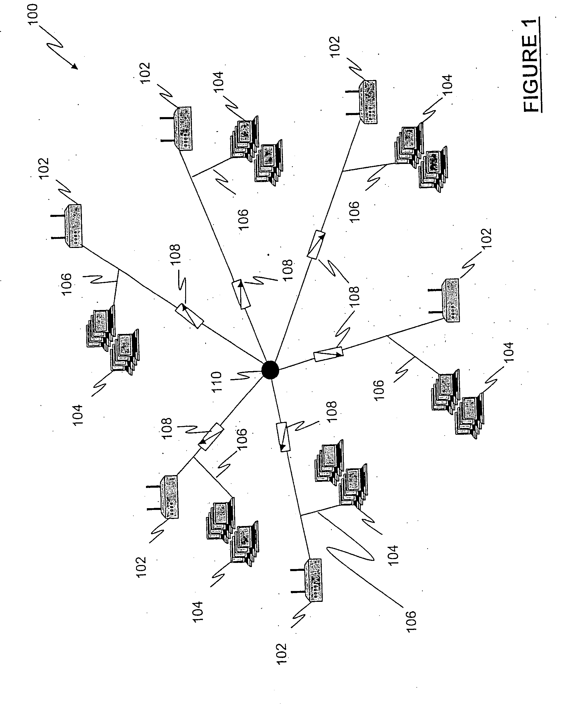
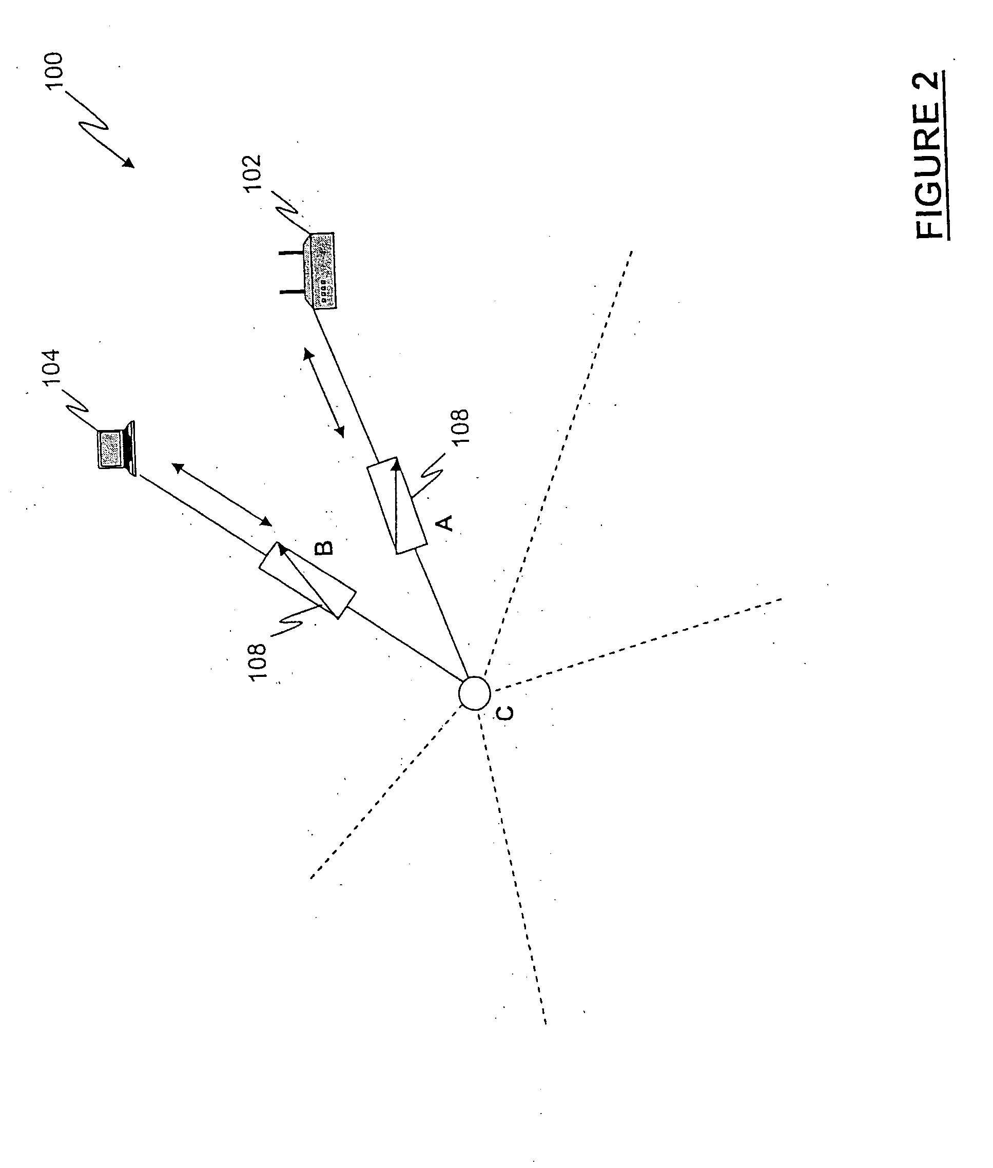
[0119] Referring to FIG. 15 and FIG. 16, a functional block diagram and a conceptual block diagram of a test system 600 are shown, respectively. Test system 600 includes a test chassis 602 having an RF combiner 604, a TestMAC module 606 and a plurality of CM's 608, wherein TestMAC module 606 and plurality of CM's 608 are communicated with RF combiner 604. RF combiner 604 is communicated with an access point 610 which is further communicated with a plurality of wireless clients 612. It will be appreciated that, in this configuration, there are shown seven CM's 608 and seven wireless clients 612, wherein each of the seven CM's 608 is associated with only one of the seven wireless clients 612 and that each CM 608 is only half populated by wireless NICs in order to simplify the explanation.

[0120] Additionally, referring to FIG. 16, a ‘group’ of multiple wireless clients 614 are shown as being representative of TestMAC module 606, wherein TestMAC module 606 is configured as a TestMAC mod...

second embodiment

[0121] Referring to FIG. 17 and FIG. 18, a functional block diagram and a conceptual block diagram of a test system 700 are shown, respectively. Test system 700 includes a test chassis 702 having an RF combiner 704, a TestMAC module 706, a plurality of CM's 708, a first RFPM 710 and a second RFPM 712, wherein TestMAC module 706, plurality of CM's 708 and first and second RFPM′710, 712 are communicated with RF combiner 704. Test system 700 also includes a first access point 714 communicated with first RFPM 710 and a second access point 716 communicated with second RFPM 712. It will be appreciated that first access point 714 and second access point 716 are connected to first RFPM 710 and second RFPM 712, respectively, through the RF test head connector 455.

[0122] It will be appreciated that this configuration advantageously permits a simple roaming scenario to be tested in which the wireless NICS, having first been associated with first access point 714 are all caused to roam to secon...

third embodiment

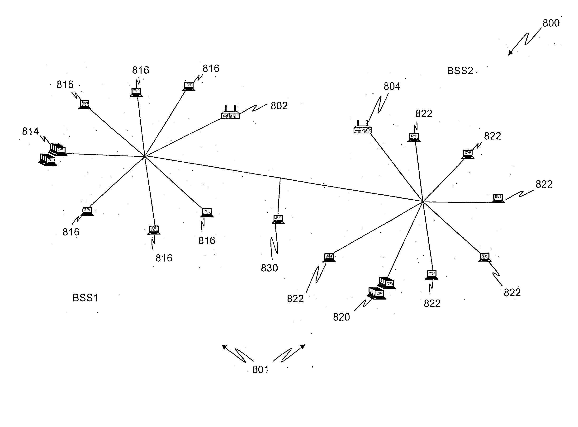
[0123] Referring to FIG. 19 and FIG. 20, a functional block diagram and a conceptual block diagram of a test system 800 are shown, respectively and depicts two Basic Service Sets (BSS) 801, each of which includes a wireless access point 102 and a plurality of wireless clients 104. Test system 800 includes a first access point 802, a second access point 804, a first test chassis 806, a second test chassis 808 and a third test chassis 810, wherein first test chassis 806, second test chassis 808 and third test chassis 810 are connected in a hierarchical manner and wherein first test chassis 806 and second test chassis 808 represent the two BSS's 801.

[0124] First test chassis 806 includes a first RF combiner 812 communicated with a first TestMAC module 814 and a plurality of first CM's 816, second test chassis 808 includes a second RF combiner 818 communicated with a second TestMAC module 820 and a plurality of second CM's 822 and third test chassis 810 includes a third RF combiner 824 ...


PUM


Abstract

A system and method for testing wireless devices in a simulated a wireless environment is provided. RF modules for creating and receiving RF signals in a test environment are also provided. Features include RF isolation of a wireless device, including filtering signals on electrical paths to and from the device, and circuits to reduce undesired RF signals on such electrical paths, for example PCI bus paths. The system and method also include a test enclosure with isolation chambers with filtered electrical signal paths to allow testing of wireless devices inserted into the isolation chambers. This system and method also allows controlled testing of antennae diversity features of the wireless device.

Description

RELATED APPLICATIONS [0001] The present application is a continuation-in-part of pending U.S. patent application Ser. No. 10 / 776,413 filed on Feb. 11, 2004, which is a continuation of application Ser. No. 10 / 379,281 filed on Mar. 4, 2003, now issued U.S. Pat. No. 6,724,730, which claims benefit of provisional patent application 60 / 361,572 filed on Mar. 4, 2002, which are incorporated herein by reference.FIELD OF THE INVENTION [0002] The present disclosure relates generally to the testing of communication devices and more particularly to a method and system for testing wireless computer network communication devices under various simulated operating conditions. BACKGROUND OF THE INVENTION [0003] Computer networks are well known and are widely used in a variety of businesses. Currently, there are many different types of wired computer networks available for personal and business use, such as Ethernet, Token-Ring, Gigabit Ethernet, ATM (Asynchronous Transfer Mode), IP, with wired Ether...

Claims


Application Information

Patent Timeline
IPC IPC(8): H04B7/08H04B17/00H04L12/24H04L12/26H04L12/28H04L12/56H04W24/06
CPCH04B7/0802H04L41/145H04B17/3912H04W24/06H04L43/50
Inventor GRIESING, JOHN ROBERTMULAWSKI, STEVEN A.FOTHERGILL, FRANCISMORAN, JAMES E.MLINARSKY, FANNY I.WRIGHT, CHARLES R.
Owner AZIMUTH NETWORKS
Why Eureka
Try Eureka