
Precision press-molding preform, process for the production thereof, optical element and process for the production of the optical element

a technology of press-molding and preforms, which is applied in the direction of manufacturing tools, instruments, lenses, etc., can solve the problems of inability to produce high-quality production, inability to achieve excellent image reproduction, and reddish image obtained, etc., to achieve stable production of optical elements, excellent near infrared absorbing function, and excellent press-molding durability

Inactive Publication Date: 2005-03-10
HOYA CORP
View PDF16 Cites 33 Cited by
  • Summary
  • Abstract
  • Description
  • Claims
  • Application Information

AI Technical Summary

Benefits of technology

[0029] According to the present invention, there can be provided a precision press-molding preform which is excellent in precision press-moldability and durability and which enables the stable production of an optical element having an excellent near infrared absorbing function, etc., and a process for the production thereof.
[0030] According to the present invention, further, there can be provided an optical element that is a precision press-molded product from the above preform and a process for the production of the optical element.
[0031] There can be therefore obtained various optical elements such as an aspherical lens, a spherical lens, a lens array, etc., which have a near infrared light absorbing function, etc., so that the optical system of a solid image-sensing device can be constituted of fewer parts, which is effective for downsizing and weight-decreasing of imaging devices. Further, since the above optical elements can be produced by precision press-molding, there can produced optical elements such as an aspherical lens, a lens array, a lens with an optical low-pass filter, a microlens, etc., easily and at a low cost, which require labors and a cost when produced by processing with a machine.

Problems solved by technology

Otherwise, an image obtained comes to be reddish, and no excellent image reproduction can be attained.
However, the above low-pass filter and the above aspherical lens have a problem that they cannot be produced highly productively when an infrared-light-absorbing glass is mechanically processed.
Since, however, a conventional near-infrared-absorbing glass contains arsenic, a large amount of P2O5 or fluorine for attaining a high transmittance at and around 400 nm, such a glass is not suitable as a glass for precision press-molding.
Arsenic involves environmental problems due to its toxicity.
Further, it exhibits very high oxidizability, so that it may damage the molding surface of a press mold used for the precision press-molding and may make it impossible to use the mold repeatedly.
Further, a glass containing a large amount of P2O5 has a problem that such a glass is poor in climate resistance.
When precision press-molding preforms are produced from such a glass and stored, the surface state of the preforms is deteriorated, and the preforms are no longer suitable as materials for producing optical elements by precision press-molding.
However, this glass has the following problem.
Since fluorine volatilizes when the glass is melted, it is difficult to. stably produce preforms one by one from the glass in a molten state, and such a glass is not suitable for the precision press-molding.
Therefore, no optical element has been put to practical use that is produced from a glass described in the above JP-A-4-104981.

Method used


Image

  • Precision press-molding preform, process for the production thereof, optical element and process for the production of the optical element
  • Precision press-molding preform, process for the production thereof, optical element and process for the production of the optical element
  • Precision press-molding preform, process for the production thereof, optical element and process for the production of the optical element

Examples


example 1

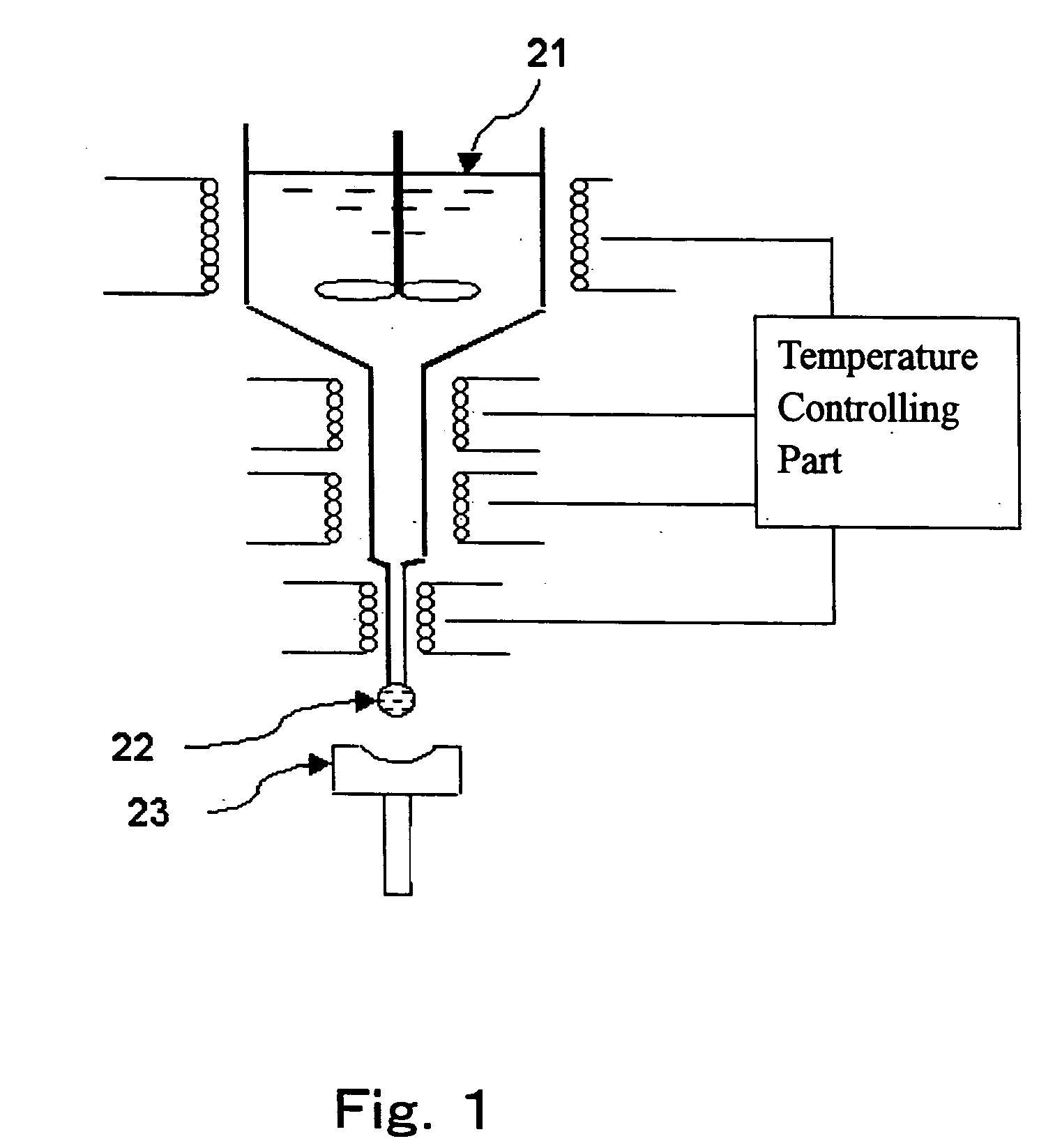
[0120] Oxides, carbonates, sulfates, nitrates, phosphates, fluorides, hydroxides, etc., as raw materials for a glass were weighed in an amount of 250 to 300 g so as to obtain a glass composition having a predetermined amount ratio shown in Table 1, and these materials were fully mixed to obtain a formulated batch. The formulated batch was placed in a platinum crucible and melted in air with stirring at a temperature of 900 to 1,100° C. for 1 to 4 hours. After melted, a clarified and homogenized molten glass was cast into a 40×70×15 mm carbon mold and gradually cooled to a temperature around the glass transition temperature thereof, and immediately thereafter, the glass is placed in an annealing furnace and annealed around the glass transition temperature for about 1 hour to allow the glass to be cooled to room temperature. The thus-obtained optical glass was observed through an optical microscope to show no precipitation of a crystal.

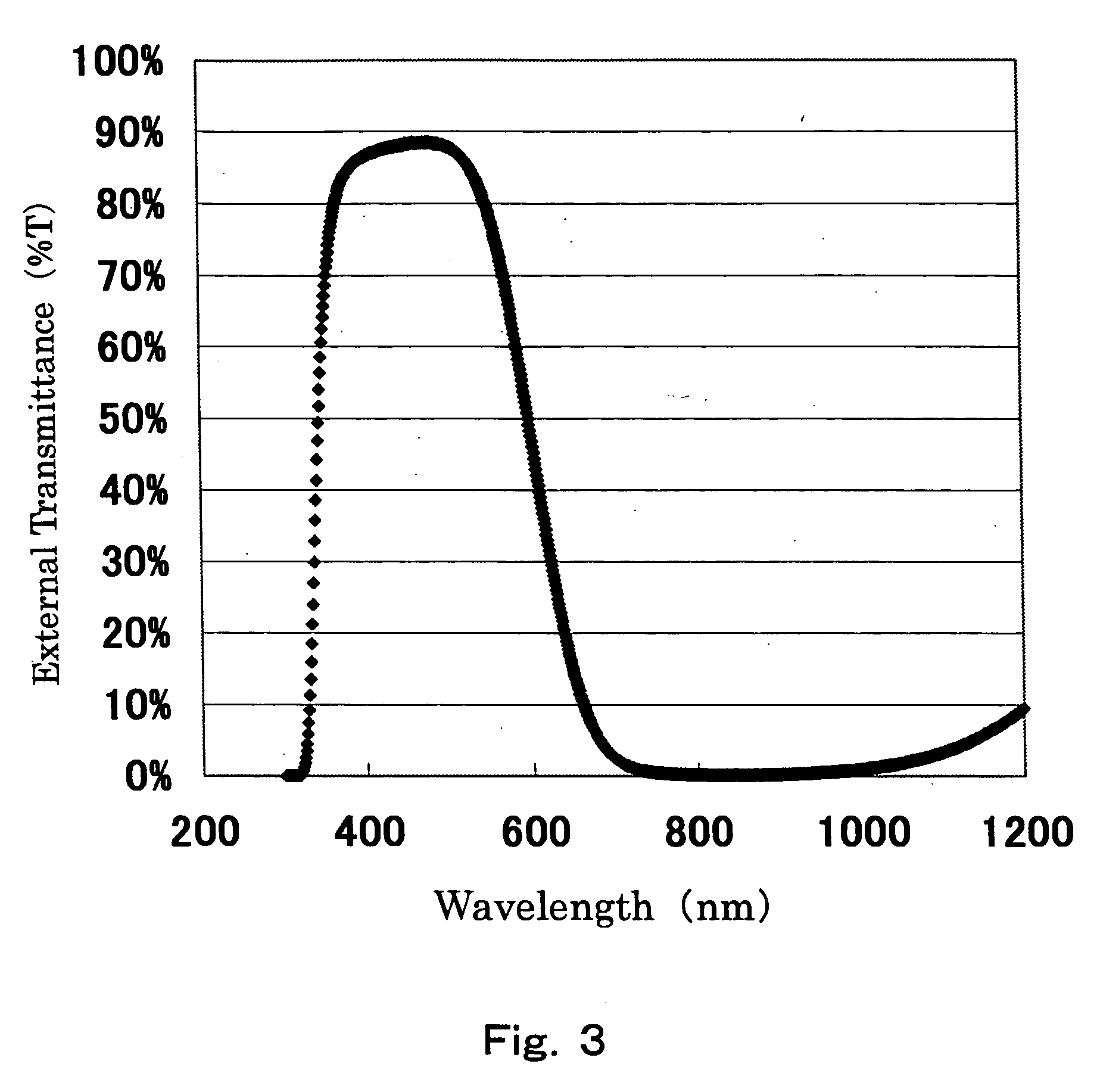
[0121] Table 2 shows external transmittances (T4...

example 2

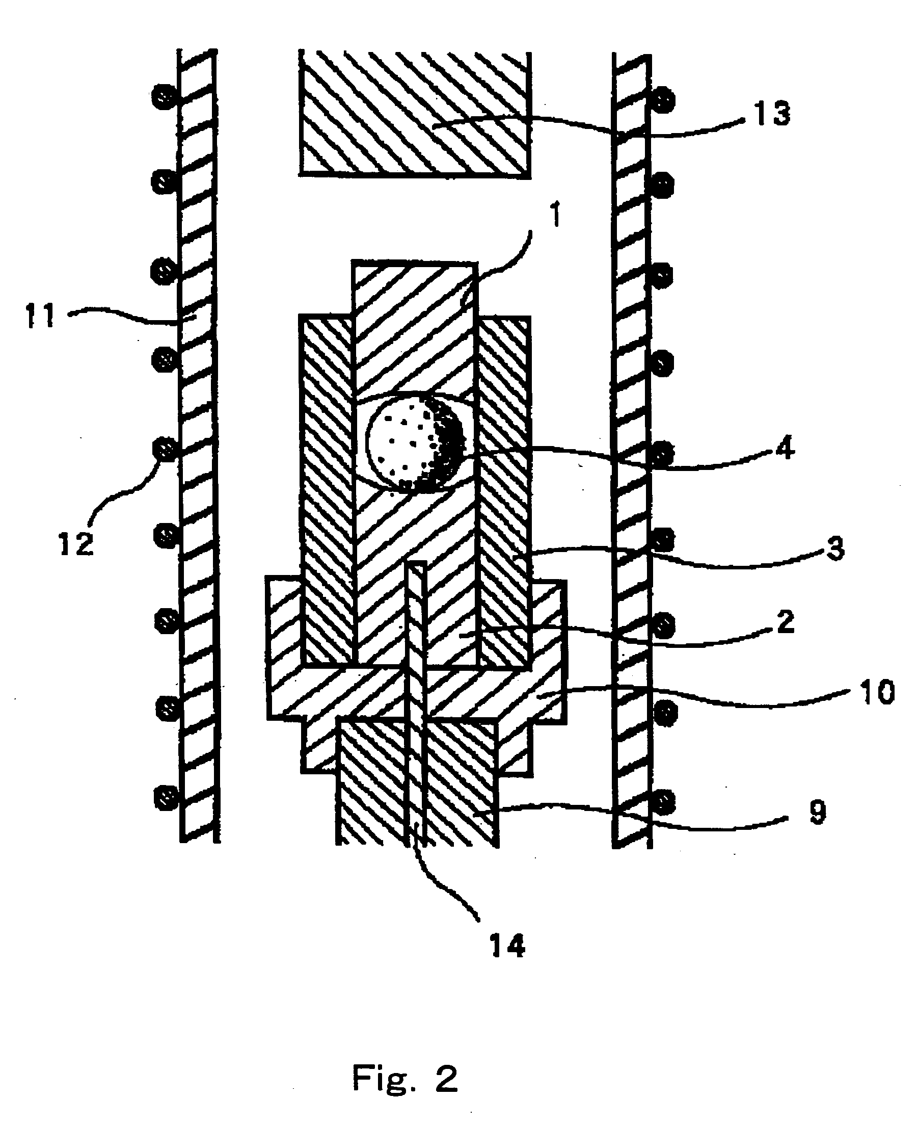
[0133]FIG. 2 shows a schematic cross-sectional view of a precision press-molding apparatus. A preform 4 that was obtained in the same manner as in Example 1 was placed between a lower mold member 2 and an upper mold member 1 of the precision press-molding apparatus shown in FIG. 2, and the atmosphere in a quartz tube 11 was replaced with a nitrogen atmosphere. A heater 12 was electrically powered to heat the quartz tube 11 internally. The temperature of the heater 12 was set such that the temperature inside a press mold was higher than the sag temperature of the glass by 20 to 60° C., and while the temperature was maintained, a pressing rod 13 was caused to move downward to press the upper mold member 1, so that the preform in the mold was precision press-molded. The molding pressure was adjusted to 8 MPa, and the molding time period was adjusted to 30 seconds. After the pressing, the molding pressure was decreased, and while the mold product was in a state where it was in contact i...


PUM

PropertyMeasurementUnit
Fractionaaaaaaaaaa
Fractionaaaaaaaaaa
Fractionaaaaaaaaaa

Abstract

A precision press-molding preform for producing an optical element for use in an imaging device using a CCD type or MOS type solid image-sensing device, which is formed of a glass composition containing, by mol %, 25 to 45% of P205, 0.5 to 10% of CuO, 0 to 10% of B203, 0 to 10% of Al203, 2 to 30% of Li2O, 0 to 25% of Na2O, 0 to 15% of K2O, the total content of Li2O, Na2O and K2O being 3 to 40%, 3 to 45% of BaO, 0 to 30% of ZnO, 0 to 20% of MgO, 0 to 20% of CaO, 0 to 20% of SrO, 0 to 10% of Bi2O3, 0 to 5% of La2O3, 0 to 5% of Gd2O3 and 0 to 5% of Y2O3, the total content of these components being at least 98%, and a precision press-molding preform, which is formed of a phosphate glass containing CuO, an alkali metal oxide, BaO and ZnO and having a BaO content / ZnO content molar ratio (BaO / ZnO) of greater than 1.

Description

FIELD OF THE INVENTION [0001] The present invention relates to a precision press-molding preform (a preform for precision press-molding) and a process for the production thereof and also relates to an optical element and a process for the production thereof. More specifically, the present invention relates to a precision press-molding preform, the preform being formed of a phosphate glass and being for an optical element to be encased in an imaging device of a color VTR or digital camera using a solid image sensing device of a CCD (Charge-Coupled Device) type or MOS (Metal-Oxide-Semiconductor) type, and a process for the production thereof. And, it also relates to various optical elements formed from such preforms by precision press-molding, particularly, an optical element having a near infrared absorbing function, and a process for the production thereof. TECHNICAL BACKGROUND [0002] Conventionally, most of imaging devices of digital cameras and digital VTR cameras use CCD and MOS ...

Claims


Application Information

Patent Timeline
IPC IPC(8): G02B1/00C03B7/12C03B11/12C03C3/16C03C3/17C03C3/19C03C4/08G02B3/00
CPCC03B7/12C03C3/17C03B11/122Y02P40/57
Inventor FUJIWARA, YASUHIROZOU, XUELU
Owner HOYA CORP
Learn More