Perylene derivative synthesis process, perylene derivative and organic EL device

a technology of perylene derivative and synthesis process, which is applied in the field of organic electroluminescent devices, can solve the problems of limiting the degree of freedom of compound design, low preparation efficiency, and low efficiency of prior art synthesis procedures

Inactive Publication Date: 2005-03-10
FUTABA CORPORATION
View PDF5 Cites 11 Cited by
  • Summary
  • Abstract
  • Description
  • Claims
  • Application Information

AI Technical Summary

Benefits of technology

An object of the invention is to provide a perylene derivative synthesis process featuring a satisfactory yield and improved preparation efficiency, a perylene derivative obtained by the process, and an organic EL device using the same.

Problems solved by technology

However, these prior art synthesis procedures suffer from the problem of very low efficiency because the end products are obtained in yields of at most 20%.
Although the prior art synthesis procedures are relatively easy to synthesize an end product having symmetry, they encounter a problem when it is desired to obtain an end product having no symmetry.
That is, since it is difficult to directly synthesize the asymmetric end product, the asymmetric end product must be separated from a variety of reaction products, which indicates a very low preparation efficiency and restricts the degree of freedom of compound design.

Method used


Image

  • Perylene derivative synthesis process, perylene derivative and organic EL device
  • Perylene derivative synthesis process, perylene derivative and organic EL device
  • Perylene derivative synthesis process, perylene derivative and organic EL device

Examples


first embodiment

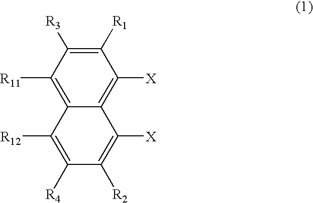
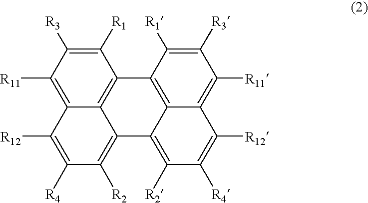
the inventive synthesis process involves halogenating a 1,8-dihalogenated naphthalene derivative of the following formula (1), and subjecting it to coupling reaction for thereby synthesizing a perylene derivative of the following formula (2).

Referring to formula (1), R1 to R4, R11 and R12 each are a hydrogen atom, a straight, branched or cyclic alkyl radical which may be substituted, a straight, branched or cyclic alkoxy radical which may be substituted, a straight, branched or cyclic alkylthio radical which may be substituted, a straight, branched or cyclic alkenyl radical which may be substituted, a straight, branched or cyclic alkenyloxy radical which may be substituted, a straight, branched or cyclic alkenylthio radical which may be substituted, a substituted or unsubstituted aralkyl radical, a substituted or unsubstituted aralkyloxy radical, a substituted or unsubstituted aralkylthio radical, a substituted or unsubstituted aryl radical, a substituted or unsubstituted aryloxy r...

second embodiment

the inventive synthesis process involves using a 1,8-dihalogenated naphthalene derivative of formula (1) and a naphthyl-1,8-diboronic acid derivative of the following formula (7), and subjecting them to Suzuki coupling reaction for thereby synthesizing a perylene derivative of formula (2).

In formula (7), Z is a boronic acid derivative, and R1 to R4, R11 and R12 are as defined for R1 to R4, R11 and R12 in formula (1). As the boronic acid derivative represented by Z, boronic acid B(OH)2 is often used although derivatives having equivalent action are inclusive.

In Suzuki coupling reaction, the compounds of formulae (1) and (7) are treated in a solvent which inert to the reaction, in the presence of a base and a palladium catalyst, and at a temperature of room temperature to 125° C. for 10 minutes to 24 hours, obtaining a reaction product.

The solvent used herein is not critical, and examples thereof include aromatic hydrocarbons (e.g., benzene and toluene), ethers (e.g., tetrahydrof...

third embodiment

the invention is a combination of halogenation followed by coupling according to the first embodiment with coupling via boron derivative according to the second embodiment. That is, the third embodiment is a perylene derivative synthesis process involving using a naphthalene derivative of the following formula (13) and subjecting it to Suzuki coupling reaction for thereby synthesizing a desired perylene derivative.

X is Cl, Br or I, and Z is a boronic acid derivative. R1 to R4, R11 and R12 in formula (13) are as defined in formula (1). X and Z are the same as in the first and second embodiments, with their preferred examples being also the same. The same applies to formulae (14) and (15) below.

Also, a perylene derivative can be synthesized by using a fluoranthene derivative of the following formula (14), and subjecting it to Suzuki coupling reaction.

X is Cl, Br or I, and Z is a boronic acid derivative. R1 to R6, R21 and R22 in formula (14) are as defined in formula (3).

Furthe...


PUM

PropertyMeasurementUnit
voltageaaaaaaaaaa
electric fieldaaaaaaaaaa
luminescentaaaaaaaaaa

Abstract

The invention aims to provide a perylene derivative preparation process featuring satisfactory yields and improved preparation efficiency, a perylene derivative obtained by the process, and an organic EL device using the same. The object is achieved by a perylene derivative preparation process comprising subjecting to coupling reaction a 1,8-dihalogenated naphthalene derivative of the formula (1): wherein X is Cl, Br or I, R1 to R4, R11 and R12 each are hydrogen, alkyl, alkoxy, alkylthio, alkenyl, alkenyloxy, alkenylthio, aralkyl, aralkyloxy, aralkylthio, aryl, aryloxy, and arylthio radicals which may be substituted, amino radical, cyano radical, hydroxyl radical, —COOM1 radical (wherein M1 is hydrogen, alkyl, alkenyl, aralkyl or aryl), —COM2 radical (wherein M2 is hydrogen, alkyl, alkenyl, aralkyl, aryl or amino), or —OCOM3 radical (wherein M3 is alkyl, alkenyl, aralkyl or aryl), and at least two adjoining radicals selected from among R1 to R4, R11 and R12 may bond or fuse together to form a substituted or unsubstituted carbocyclic aliphatic ring, aromatic ring or fused aromatic ring with the carbon atoms on which they substitute, with the proviso that when the carbocyclic aliphatic ring, aromatic ring or fused aromatic ring has substituent radicals, the substituent radicals are the same as R1 to R4, R11 and R12, to thereby synthesize a perylene derivative of the formula (2): wherein R1′ to R4′, R11′ and R12′ are as defined for R1 to R4, R11 and R12 in formula (1), and R1 to R4, R11 and R12 and R1′ to R4′, R11′ and R12′ may be the same or different.

Description

BACKGROUND OF THE INVENTION 1. Field of the Invention This invention relates to an organic electroluminescent (EL) device, and more particularly, to a compound for use in a device of the type wherein an electric field is applied across a thin film of an organic compound to emit light. 2. Background Art Organic electroluminescent (EL) devices include a thin film containing a luminescent organic compound interleaved between an electron injecting electrode and a hole injecting electrode. Electrons and holes are injected into the thin film where they are recombined to create excitons. Light is emitted by utilizing luminescence (phosphorescence or fluorescence) upon deactivation of excitons. The organic EL devices are characterized by plane light emission at a high luminance of about 100 plus to about 10,000 plus cd / m2 with a voltage of about 10 volts and light emission in a spectrum from blue to red color by a simple choice of the type of fluorescent material. Doping is one techni...

Claims


Application Information

Patent Timeline
Patent Type & Authority Applications(United States)
IPC IPC(8): C07C13/62C07C15/20C07C17/30C07C17/35C07C25/22C07C25/24H01L51/00H01L51/30H01L51/40H01L51/50
CPCC07C13/62Y10S428/917C07C17/30C07C17/35C07C25/22C07C25/24C07C2103/52C07C2103/54H01L51/001H01L51/0052H01L51/0055H01L51/0056H01L51/0058H01L51/0059H01L51/0081H01L51/5012H01L2251/308C07C15/20C07C2603/52C07C2603/54H10K71/164H10K85/615H10K85/623H10K85/624H10K85/626H10K85/631H10K85/324H10K50/11H10K2102/103
Inventor FUJITA, TETSUJIARA, KENSUKEINOUE, TETSUSHI
Owner FUTABA CORPORATION
Why Eureka
Try Eureka