Multi-step magnetron sputtering process
a magnetron sputtering and multi-step technology, applied in the field of plasma sputtering, can solve the problems of high aspect ratio, inability to easily classify barriers, and inability to sputter, and achieve the effect of improving the conformality of a layer and high-energy ionized target materials
- Summary
- Abstract
- Description
- Claims
- Application Information
AI Technical Summary
Benefits of technology
Problems solved by technology
Method used
Image
Examples
first embodiment
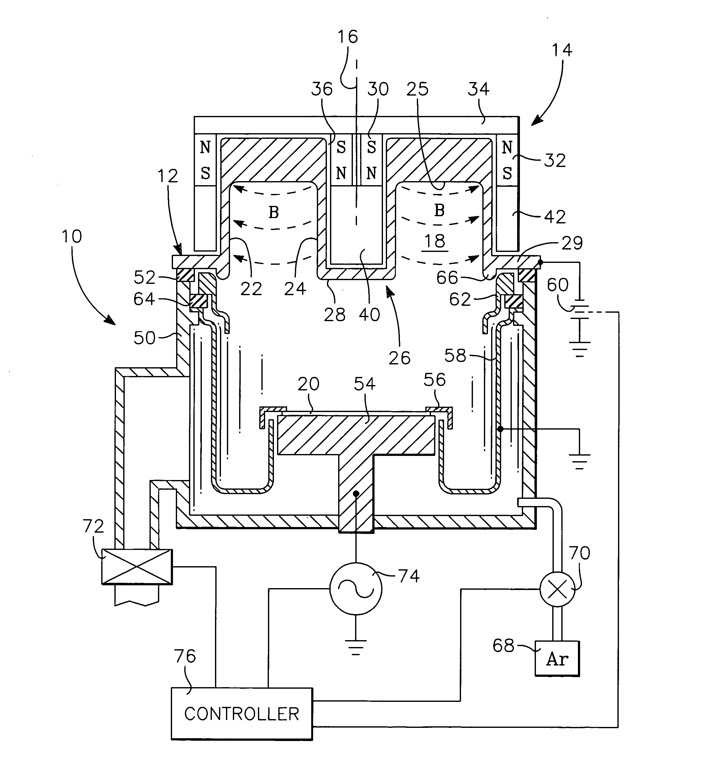
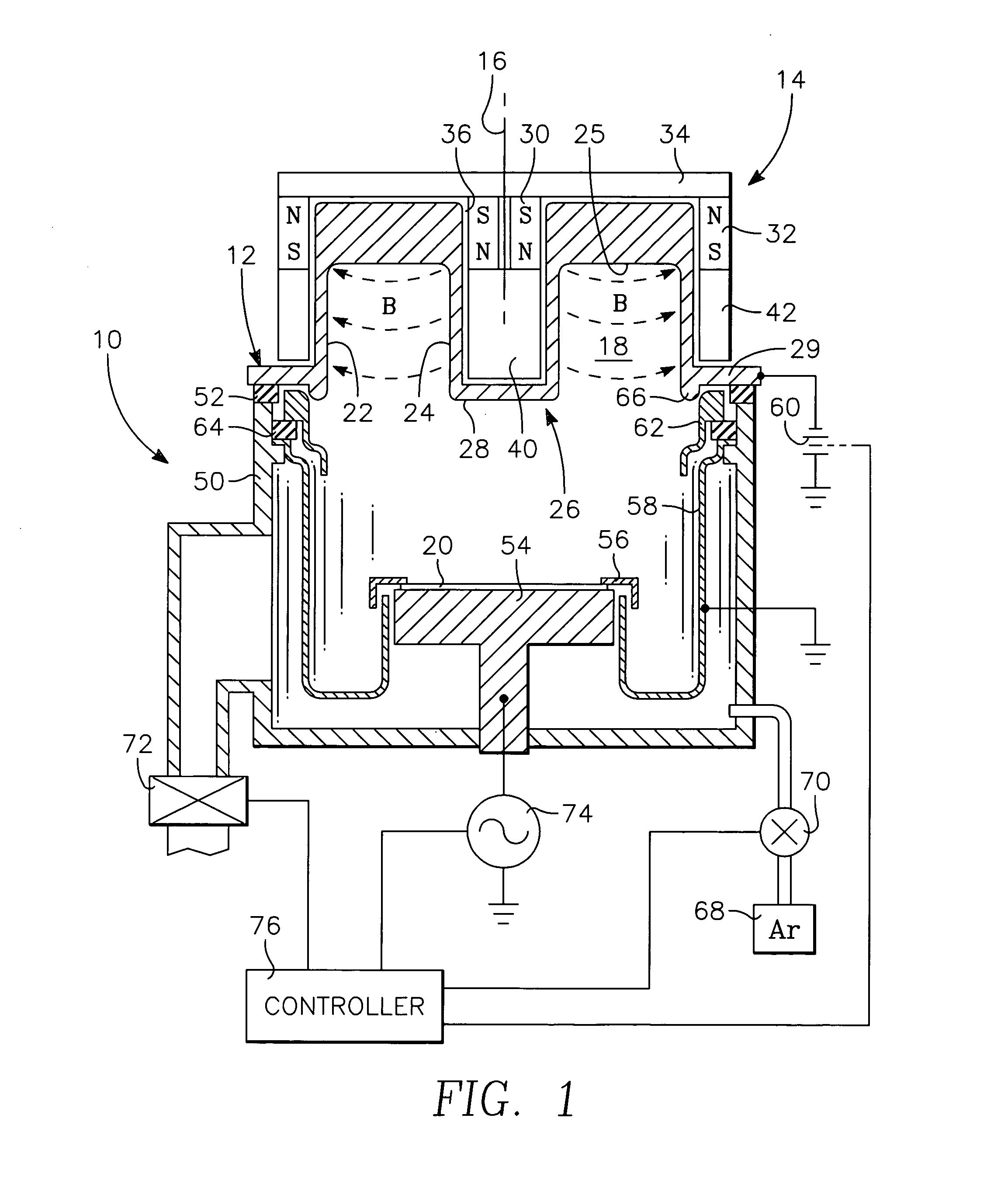
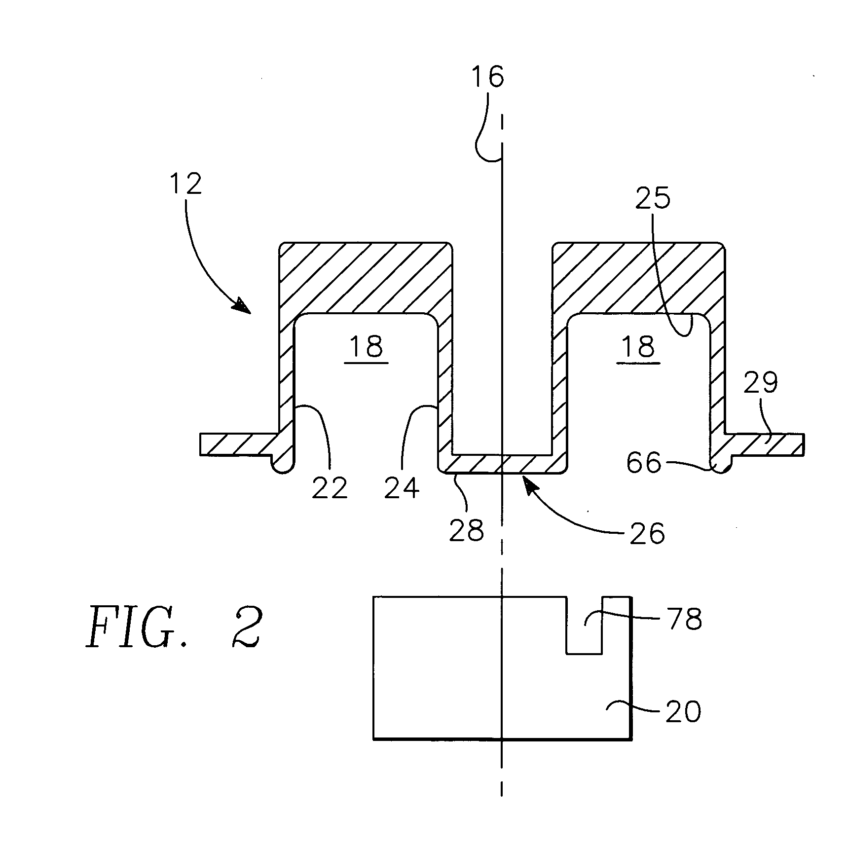
[0053] A magnetron sputter reactor 10 of the invention is illustrated in the schematic cross-sectional view of FIG. 1. It includes a specially shaped sputter target 12 and magnetron 14 symmetrically arranged about a central axis 16 in a reactor otherwise described for the most part by Chiang et al. in the above referenced patent application. This reactor and associated processes will be referred to as SIP+ sputtering in contrast to the SIP sputter reactor of Chiang et al., which uses a planar target. The shaped target 12 or at least its interior surface is composed of the material to be sputter deposited. The invention is particularly useful for sputtering copper, but it may be applied to other sputtering materials as well. It is understood that target may be composed of alloys, typically to less than 10% of alloying. For example, copper is often alloyed with silicon, aluminum, or magnesium. As is known, reactive sputtering of materials like TiN and TaN can be accomplished by using ...
second embodiment
[0064] A sputter reactor 80 of second embodiment of the invention is illustrated in the schematic cross-sectional view of FIG. 3. A magnetron 82 includes the previously described inner magnets 30 and inner pole piece 40. However, one or more outer magnets 84 and an outer pole piece 86 extend around only a segment of the circumference of the target, for example between 15° and 90°. An asymmetric magnetic yoke 88 shaped as a sector magnetically couples the inner and outer magnets 30, 84 but only on the side of target well 36 toward the outer magnets 84. In fact, a circular yoke 88, although larger, would not affect the operative magnetic field. As a result, a high-density plasma is generated in only a small circumferential portion of the target vault 18. For self-ionized plating (SIP) and particularly sustained self-sputtering (SSS), a high plasma density is desired. In view of the limited capacity of realistic power supplies 60, the high plasma density can be achieved by reducing the...
third embodiment
[0066] Other magnet configurations are possible to produce similar magnetic field distributions. A sputter reactor 100 of the invention is illustrated in the schematic cross-sectional view of FIG. 4A magnetron 102 includes an inner magnet 104 having a magnetization direction generally aligned with a radius of the target 12 about the target axis 16. One or more outer magnets 106 are similarly radially magnetized but anti-parallel to the magnetization of the inner magnet 104 with respect to the center of the vault 18. A C-shaped magnetic yoke has two arms 110, 112 in back of and supporting the respective magnets 104, 106 and a connector 114 supported on and rotated by the shaft of the motor 90.
[0067] The magnets 104, 106 may be advantageously positioned only on reduced circumferential portions of the sidewalls 24, 22 of the target vault 18 so as to concentrate the magnetic field there. Furthermore, in this configuration extending along only a small segment of the target periphery, the...
PUM
| Property | Measurement | Unit |
|---|---|---|
| width | aaaaa | aaaaa |
| width | aaaaa | aaaaa |
| width | aaaaa | aaaaa |
Abstract
Description
Claims
Application Information
 - R&D
- Intellectual Property
- Life Sciences
- Materials
- Tech Scout
- Unparalleled Data Quality
- Higher Quality Content
- 60% Fewer Hallucinations
Browse by: Latest US Patents, China's latest patents, Technical Efficacy Thesaurus, Application Domain, Technology Topic, Popular Technical Reports.
© 2025 PatSnap. All rights reserved.Legal|Privacy policy|Modern Slavery Act Transparency Statement|Sitemap|About US| Contact US: help@patsnap.com


