
Polymer, resist composition and patterning process

Active Publication Date: 2005-03-17
SHIN ETSU CHEM IND CO LTD
View PDF13 Cites 20 Cited by
  • Summary
  • Abstract
  • Description
  • Claims
  • Application Information

AI Technical Summary

Benefits of technology

The inventive resist composition prepared using the inventive polymer as a base resin lends itself to micropatterning with electron beams or deep UV since it is sensitive to high-energy radiation and is improved in sensitivity, resolution and etching resistance. Especially because of the minimized absorption at the exposure wavelength of an ArF or KrF excimer laser, the composition can be processed by photolithography using such a laser, to form a finely defined pattern having sidewalls perpendicular to the substrate.

Problems solved by technology

Introduction of more acid labile units is advantageous in achieving a higher sensitivity and contrast, but gives rise to the problem of exaggerated pattern density-dependent size difference.
This suggests a contradiction that a larger amount of acid labile units sufficient to provide a higher sensitivity and resolution is unacceptable for practical use because of exaggerated pattern density-dependent size difference whereas a smaller amount of acid labile units provides an acceptable level of pattern density-dependent size difference, but impractical levels of sensitivity and resolution.

Method used


Image

  • Polymer, resist composition and patterning process
  • Polymer, resist composition and patterning process
  • Polymer, resist composition and patterning process

Examples


synthesis example 1

Synthesis of Polymer 1

A mixture of 82.9 g of 2-methyl-2-adamantyl methacrylate, 10.2 g of methacrylic acid, 60.8 g of 3-hydroxy-1-adamantyl methacrylate, 96.2 g of 9-methoxycarbonyl-4-oxa-5-oxotricyclo[4.2.1.03,7]nonan-2-yl methacrylate, 0.84 g of 2-mercaptoethanol and 750 g of tetrahydrofuran was heated at 60° C. To the solution was added 5.28 g of 2,2′-azobisisobutyronitrile. The solution was stirred for 20 hours while keeping at 60° C. The reaction solution was cooled to room temperature, after which with vigorous stirring, it was added dropwise to 10 liters of hexane. The resulting solids were collected by filtration and dried in vacuum at 40° C. for 15 hours, obtaining a polymer (designated Polymer 1) in white powder solid form. The amount was 223.0 g and the yield was 89.2%. An integration ratio computed from a 1H-NMR spectrum indicated an approximate copolymer compositional ratio of 30 / 10 / 25 / 35. Polymer 1 had a Mw of 6,600.

synthesis examples 2-164

Synthesis of Polymers 2-164

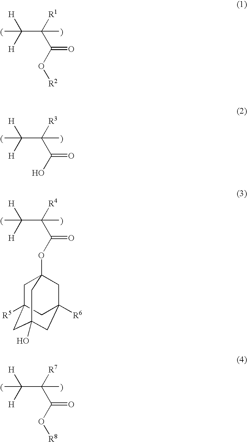
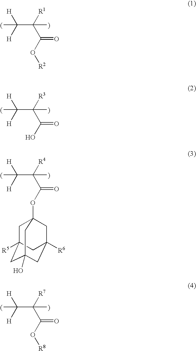
Polymers 2 to 164 as shown in Tables 1 to 4 were synthesized by the same procedure as above or a well-known procedure. In Tables 1 to 4, the recurring units included in the copolymers are represented by the following abbreviations. That is, the recurring units of formula (1) are designated as (1A) to (1P), the recurring units of formula (2) are designated as (2A) and (2B), the recurring units of formula (3) are designated as (3A) to (3F), and the recurring units of formula (4) are designated as (4A) to (4P).

TABLE 1RecurringRecurringRecurringRecurringCompositionalPolymer No.unit (1)unit (2)unit (3)unit (4)ratioMwPolymer 11A2A3A4D30 / 10 / 25 / 356600Polymer 21A2A3A4H30 / 10 / 25 / 356500Polymer 31A2A3A4H50 / 10 / 20 / 206700Polymer 41B2A3A4D30 / 10 / 25 / 355600Polymer 51B2A3A4H30 / 10 / 25 / 355400Polymer 61B2A3A4H50 / 10 / 20 / 205000Polymer 71C2A3A4D30 / 10 / 25 / 357600Polymer 81C2A3A4H30 / 10 / 25 / 357500Polymer 91C2A3A4H50 / 10 / 20 / 207800Polymer 101D2A3A4H30 / 10 / 25 / 357000Polymer 111E2A3A4D30 / 10 / 2...

examples

Resist compositions were formulated using inventive polymers and examined for resolution.


PUM

PropertyMeasurementUnit
Fractionaaaaaaaaaa
Fractionaaaaaaaaaa
Nanoscale particle sizeaaaaaaaaaa

Abstract

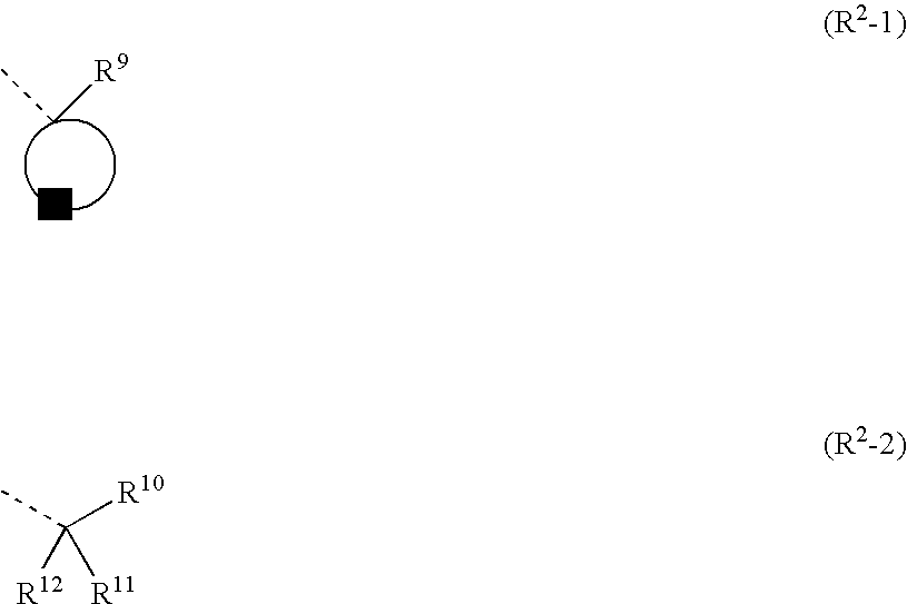
A polymer comprising recurring units of formulae (1) to (4) wherein R1, R3, R4 and R7 are hydrogen or methyl, R2 is an acid labile group, R5 and R6 are hydrogen or hydroxyl, and R8 is a lactone structure group and having a Mw of 1,000-50,000 is provided. A resist composition comprising the inventive polymer has a sensitivity to high-energy radiation, improved resolution and etching resistance and lends itself to lithographic micropatterning with electron beams or deep UV.

Description

CROSS-REFERENCE TO RELATED APPLICATIONS This non-provisional application claims priority under 35 U.S.C. Section 119(a) on Patent Application No. 2003-320659 filed in Japan on Sep. 12, 2003, the entire contents of which are incorporated herein by reference. TECHNICAL FIELD This invention relates to (i) a novel polymer for resist use, (ii) a resist composition comprising the polymer as a base resin for use in the micropatterning technology, and (iii) a patterning process using the resist composition. BACKGROUND OF THE INVENTION While a number of recent efforts are being made to achieve a finer pattern rule in the drive for higher integration and operating speeds in LSI devices, deep-ultraviolet lithography is thought to hold particular promise as the next generation in microfabrication technology. In particular, photolithography using a KrF or ArF excimer laser as the light source is strongly desired to reach the practical level as the micropatterning technique capable of achievin...

Claims


Application Information

Patent Timeline
IPC IPC(8): G03C1/76G03F7/039
CPCY10S430/111G03F7/0397G03F7/039
Inventor TACHIBANA, SEIICHIRONISHI, TSUNEHIROKOBAYASHI, TOMOHIRO
Owner SHIN ETSU CHEM IND CO LTD
Learn More