Laser ablation feedback spectroscopy

a technology of feedback spectroscopy and laser ablation, which is applied in the direction of manufacturing tools, metal working equipment, welding/soldering/cutting articles, etc., can solve the problems of workpiece surface contamination, interference with optical or fluidic properties, and debris may be extremely difficult to remove from the surface of some materials

Inactive Publication Date: 2005-03-24
BLUMENFELD WALTER +2
View PDF8 Cites 117 Cited by
  • Summary
  • Abstract
  • Description
  • Claims
  • Application Information

AI Technical Summary

Benefits of technology

[0020] (7) A seventh embodiment of the invention places the sampling aperture of a fiber-coupled spectrometer (remotely located) so that it has the laser ablation plasma in its field of view. When the laser begins to ablate material from a deeper layer of composite work-piece material, the emission spectrum will change. The plasma emission in view of the sampling aperture follows this change and the fiber-coupled spectrometer interprets it and forwards a signal to the laser controller to terminate ablation. This provides accurate depth control in composite material ablation.

Problems solved by technology

One of the long-standing technical problems in laser micro-machining is work-piece surface contamination by ablated material which falls back on the surface in the area of the laser focus and adheres to it.
Such contamination may cause undesirable physical surface artifacts, which may interfere with optical or fluidic properties in the intended use of the work-piece.
Furthermore, such debris may be extremely difficult to remove from the surface of some materials.
Unfortunately, as the geometry of the laser focus is reduced in size and instantaneous laser power is increased, this technique becomes less effective.
Another technical problem in application of laser drilling in composite or layered materials (especially for the semiconductor manufacturing industry) is accurate depth control for laser-drilling blind holes.

Method used


Image

  • Laser ablation feedback spectroscopy
  • Laser ablation feedback spectroscopy
  • Laser ablation feedback spectroscopy

Examples


first embodiment

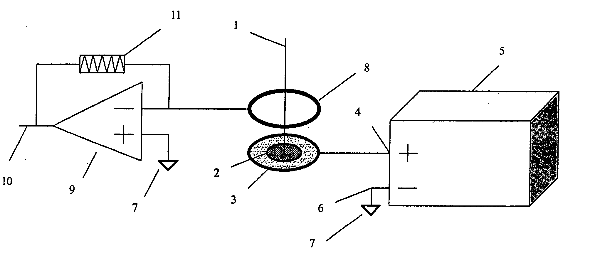
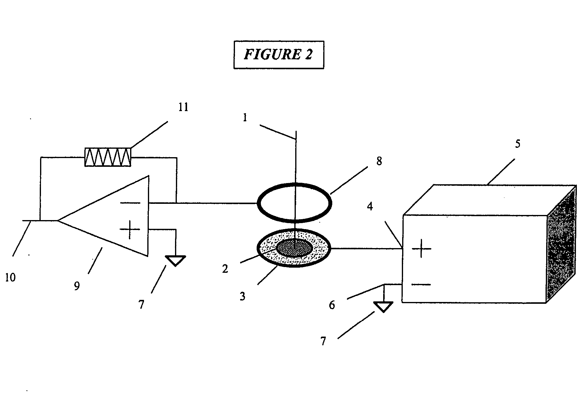
[0030] the present invention is depicted in FIG. 1. The optical axis 1 of a laser ablation device (not shown) is centered on a work-piece 2, which is retained in an electrically conductive chuck or holding fixture 3. The work-piece 2 and holder 3 are connected to a DC power supply 5 by a wire 4 attached to its positive output. The negative output of power supply 5 is connected by another wire 6 to earth ground 7. This circuit places a positive voltage potential on the work-piece 2 surface. A circular electrode ring 8 connected to earth ground 7 is located above the work-piece 2 and centered about the optical axis 1; this establishes an electric field above the work-piece such that positively ionized particles from the laser ablation plume are attracted to the electrode ring. Furthermore, any positively charged particles from the ablation plume that escape attraction to the electrode ring (by virtue of excess kinetic energy) are repulsed from the positively charged surface of the wor...

second embodiment

[0032] the invention is shown in cross-section in FIG. 3. The work-piece 2 is supported in the holder 3. A first conductive mask or film 12 is located in intimate contact with the upper surface of the work-piece 2, and retained by any method such as an adhesive, clamps or gravity. The first conductive mask or film 12 is connected by wire 4 to the positive output of a DC power supply 5, whose negative output is connected to earth ground 7. An insulating mask or film 13 is applied to the upper surface of the first conductive mask or film 12. A second conductive mask or film 14 is applied to the upper surface of the insulating mask or film 13 and connected to earth ground 7. As the laser ablation proceeds along the optical axis 1, it ablates through the successive layers of masks 14, 13, 12 and then commences to ablate the work-piece 2. The positively ionized particles in the ablation plume are repelled by the positively charged first conductive film or mask 12 on the upper work-piece ...

fourth embodiment

[0034] the invention is shown in FIG. 5. A permanent magnet 17 is located near the optical axis near the ablation site on the work-piece 2. The magnetic field deflects the charged particles in the ablation plume through a curved path 18, whose radius and direction are dependent on the strength and geometry of the magnetic field, the mass / charge ratio of each particle in the plume, and the initial velocity vector of each particle. The same result is achieved as shown in FIG. 6, in which a DC electromagnet 19 energized by windings 20 creates the magnetic deflection field.


PUM

PropertyMeasurementUnit
electric fieldaaaaaaaaaa
voltage potentialaaaaaaaaaa
mass analyzeraaaaaaaaaa

Abstract

Methods, for use with a laser ablation or drilling process, which achieve depth-controlled removal of composite-layered work-piece material by real-time feedback of ablation plasma spectral features. The methods employ the use of electric, magnetic or combined fields in the region of the laser ablation plume to direct the ablated material. Specifically, the electric, magnetic or combined fields cause the ablated material to be widely dispersed, concentrated in a target region, or accelerated along a selected axis for optical or physical sampling, analysis and laser feedback control. The methods may be used with any laser drilling, welding or marking process and are particularly applicable to laser micro-machining. The described methods may be effectively used with ferrous and non-ferrous metals and non-metallic work-pieces. The two primary benefits of these methods are the ability to drill or ablate to a controlled depth, and to provide controlled removal of ablation debris from the ablation site. An ancillary benefit of the described methods is that they facilitate ablated materials analysis and characterization by optical and/or mass spectroscopy.

Description

CROSS-REFERENCE TO RELATED APPLICATIONS [0001] The present application derives priority from U.S. Provisional Patent Application 60 / 492, filed: Aug. 6, 2003BACKGROUND OF THE INVENTION [0002] 1. Field of Invention [0003] The present invention relates to laser drilling, marking and welding, and more particularly, to reduction of work-piece surface contamination by ablation debris, and to precision depth control of laser ablation. [0004] 2. Description of the Background [0005] One of the long-standing technical problems in laser micro-machining is work-piece surface contamination by ablated material which falls back on the surface in the area of the laser focus and adheres to it. Such contamination may cause undesirable physical surface artifacts, which may interfere with optical or fluidic properties in the intended use of the work-piece. Furthermore, such debris may be extremely difficult to remove from the surface of some materials. [0006] One common practice for controlling ablatio...

Claims


Application Information

Patent Timeline
Patent Type & Authority Applications(United States)
IPC IPC(8): B23K26/03B23K26/06B23K26/36B23K26/38
CPCB23K26/03B23K26/032B23K26/0656B23K26/123B23K26/367B23K26/4085B23K2201/40B23K26/4005B23K26/401B23K26/4025B23K26/381B23K26/364B23K26/382B23K26/066B23K26/40B23K2101/40B23K2103/16B23K2103/172B23K2103/50
Inventor BLUMENFELD, WALTERD'ENTREMONT, JOSEPHGIDNER, ROBERT
Owner BLUMENFELD WALTER
Why Eureka
Try Eureka