Hydrogen diffusion electrode for protonic ceramic fuel cell

a ceramic fuel cell and hydrogen diffusion electrode technology, applied in the direction of cell components, final product manufacturing, sustainable manufacturing/processing, etc., can solve the problems of limiting the generation of electric current, affecting the efficiency of fuel cells, and affecting the production efficiency of fuel cells

Inactive Publication Date: 2005-03-24
PROTONETICS INT
View PDF6 Cites 31 Cited by
  • Summary
  • Abstract
  • Description
  • Claims
  • Application Information

AI Technical Summary

Benefits of technology

Embodiments of the invention also include a method of generating molecular oxygen and hydrogen from a proton conducting fuel cell having a positive and negative electrode in contact with a proton conducting ceramic electrolyte. The method includes the steps of electrolyzing water vapor at a positive electrode of the fuel cell to form molecular oxygen (O2) and hydrogen ions, and reducing the hydrogen ions at a negative electrode of the fuel cell to form molecular hydrogen (H2). The electrodes are substantially non-porous and substantially impermeable to the water vapor.
Embodiments of the invention also include a method of purifying hydrogen in a proton conducting apparatus comprising a positive and negative electrode in contact with a proton conducting ceramic electrolyte. The method includes oxidizing molecular hydrogen from an impure hydrogen gas containing impurities at a positive electrode of the apparatus to form hydrogen ions, and reducing the hydrogen ions at a negative electrode of the apparatus to form substantially pure molecular hydrogen (H2). The electrodes used with the method may be substantially non-porous and substantially impermeable to the impurities.

Problems solved by technology

Even under ideal conditions typically more than half the chemical energy released in a heat engine is lost as waste heat.
Unfortunately, as direct contact between the electrode and electrolyte increases, the more difficult it is for the reactant gases to migrate to the electrode / electrolyte interface, restricting the generation of electric current.
However, liquid water or steam permeability can often be a drawback, especially when it is desired to operate the fuel cell in reverse by supplying electric power to the fuel cell in order to generate pure hydrogen by, for example, separation from a mixed gas or the electrolysis of steam.
Unfortunately, in the permeable electrode designs of conventional PEMFCs water migrates across the electrolytes with the protons and contaminates the hydrogen being produced at the anode.

Method used


Image

  • Hydrogen diffusion electrode for protonic ceramic fuel cell
  • Hydrogen diffusion electrode for protonic ceramic fuel cell
  • Hydrogen diffusion electrode for protonic ceramic fuel cell

Examples


example 1

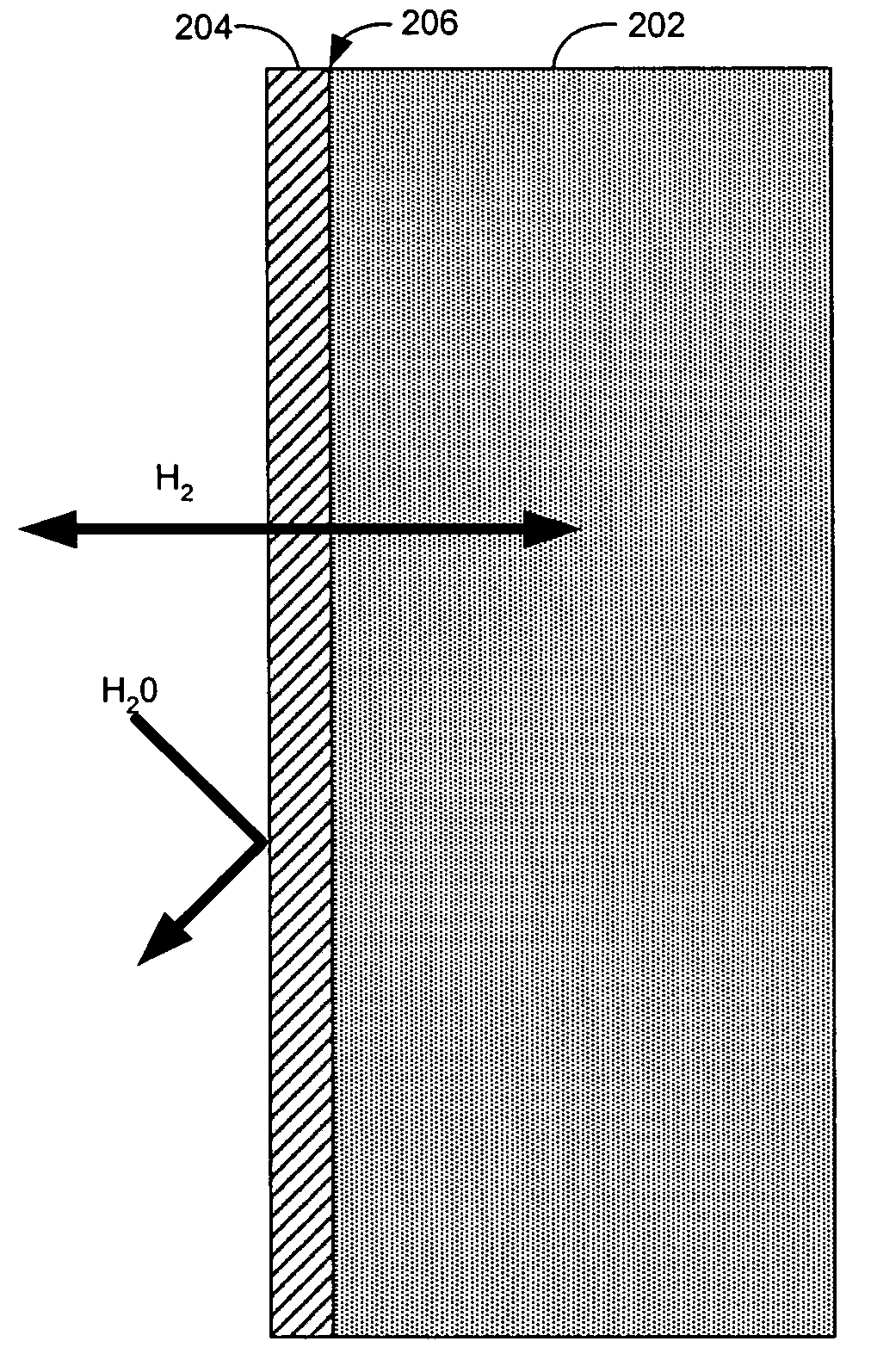
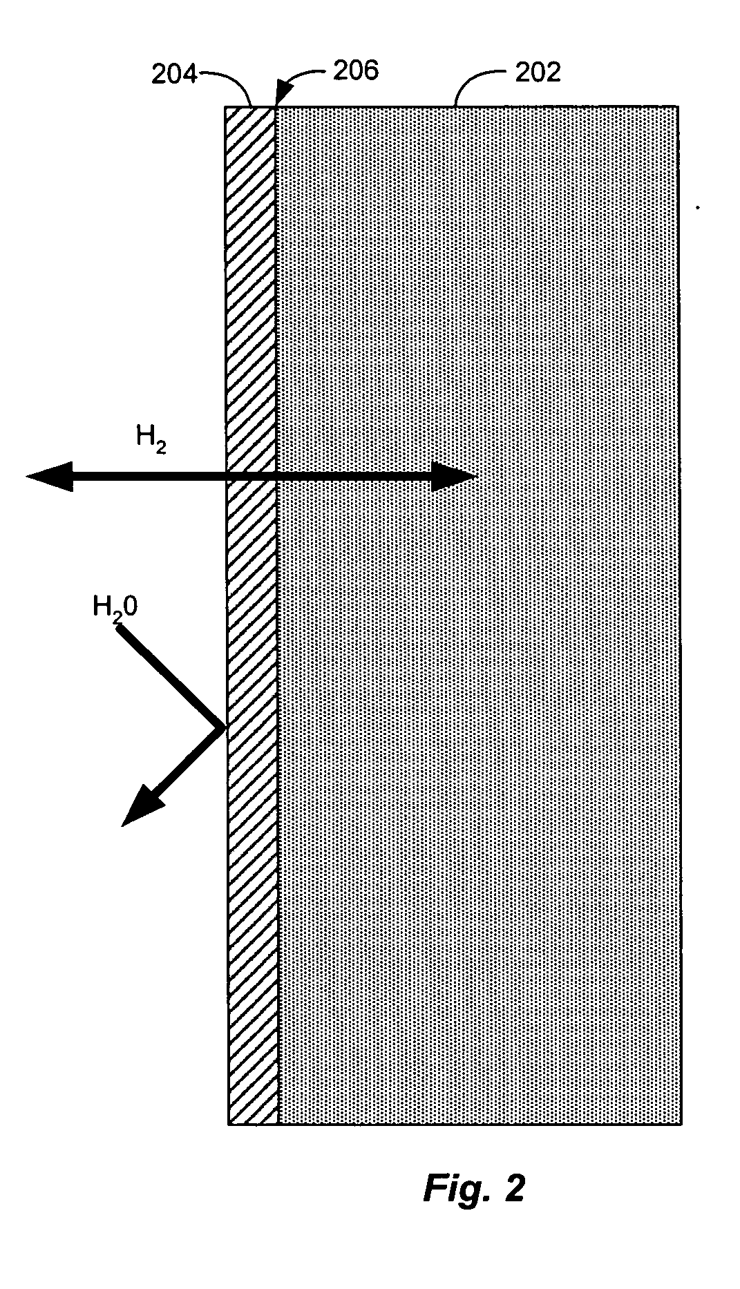
A hydrogen / air fuel cell according an embodiment of the invention was operated for 750 hours at 750° C. The fuel cell included a 1 mm thick electrolyte disc made from a solid oxide perovskite cermamic called BCY10, which has the formula BaCeo0.9Y0.1O(3-δ), where δ is about 0 to 0.10. The electrolyte was covered on the cathode side by a platinum electrode and on the anode side by a non-porous 3 μm thick sputtered nickel electrode. The fuel cell produced an average output between 30 and 40 mA / cm2 at 700 mV.

example 2

Electrical power output of a second hydrogen / air fuel cell according to an embodiment of the invention was measured. This cell included a 500 μm thick BCY10 electrolyte covered on the cathode side by a platinum electrode and on the anode side by a non-porous 2.3 μm thick nickel electrode. The fuel cell produced an average of 100 mA / cm2 at 700 mV, with a maximum power of 85 mW / cm2.

In both experiments, the fuel gas used was 99.999% dry hydrogen. No contamination or corrosion of the nickel fuel side anode electrode was observed after approximately 3 weeks continuous operation. On the cathode side of the cell, oxygen supplied by air was reduced with the migrating protons to form water. No poisoning or corrosion of the porous platinum electrode or electrolyte was observed.


PUM

PropertyMeasurementUnit
temperatureaaaaaaaaaa
thicknessaaaaaaaaaa

Abstract

A proton conducting fuel cell that includes an electrolyte having a proton conducting ceramic electrolyte and a two-phase diffusion membrane electrode contacting the electrolyte, where the electrode is substantially non-porous and permeable to hydrogen. Also, a method of generating molecular hydrogen from a proton conducting fuel cell having a positive and negative electrode in contact with a proton conducting ceramic electrolyte, including selectively extracting pure hydrogen from a hydrogen gas mixture, and electrolyzing water vapor at a positive electrode of the fuel cell to form molecular oxygen (O2) and hydrogen ions, and reducing the hydrogen ions at a negative electrode of the fuel cell to form molecular hydrogen (H2).

Description

FIELD OF THE INVENTION The present invention includes ceramic proton conducting fuel cells for the production of electrically energy or hydrogen (H2). Specifically, the fuel cells include substantially non-porous, hydrogen (e.g., proton) conducting electrodes that permit the passage of hydrogen while blocking the passage of other gases, such as steam. BACKGROUND OF THE INVENTION Fuel cells can covert the chemical energy stored in fuels into electrical energy at higher efficiencies than conventional heat engines. A conventional heat engine first converts the chemical energy to heat energy through a combustion process (e.g., reacting natural gas and oxygen to form carbon dioxide and water) and harnesses some of that heat energy for mechanical work (e.g., compressing a piston, turning a turbine blade), which then gets converted into the electrical energy. Even under ideal conditions typically more than half the chemical energy released in a heat engine is lost as waste heat. Fuel ce...

Claims


Application Information

Patent Timeline
Patent Type & Authority Applications(United States)
IPC IPC(8): C25B15/04C25B15/08H01MH01M4/90H01M4/92H01M4/94H01M8/06H01M8/10H01M8/12H01M8/18
CPCC25B15/04C25B15/08Y02E60/525H01M8/126Y02E60/521H01M8/0656Y02E60/50Y02P70/50
Inventor COORS, W. GROVER
Owner PROTONETICS INT
Why Eureka
Try Eureka