Ion mill process with sacrificial mask layer to fabricate pole tip for perpendicular recording

Inactive Publication Date: 2005-03-31
HITACHI GLOBAL STORAGE TECH NETHERLANDS BV
View PDF17 Cites 32 Cited by
  • Summary
  • Abstract
  • Description
  • Claims
  • Application Information

AI Technical Summary

Benefits of technology

[0012] It is an advantage of the present invention that the PS layer can be fabricated with a high aspect ratio which offers higher milling resistance and allows for better passivation.
[0013] It is another advantage of the present invention that better Trailing Edge structural Definition (TED) than before can be produced.
[0014] It is a further advantage of the present invention that improved Track Width Control (TWC) can be achieved. It is an advantage

Problems solved by technology

Making reliable components of such microscopic size has been a challenge to the fabricating process arts.
This problem is made even more challenging because the P3 pole shape at the ABS is preferably not a simple rectangle, but is trapezoidal, with parallel top and bottom edges, but a bevel angle preferably of approximately 8 to 15 degrees on the side edges.
Ion milling (IM) is a process that has been long used in the manufacture and shaping of such micro-components, but here there is the difficulty of maintaining the top edge dimension while trying to cut the side bevels.
The complication in developing an IM scheme is the inability to cons

Method used


Image

  • Ion mill process with sacrificial mask layer to fabricate pole tip for perpendicular recording
  • Ion mill process with sacrificial mask layer to fabricate pole tip for perpendicular recording
  • Ion mill process with sacrificial mask layer to fabricate pole tip for perpendicular recording

Examples


Example

[0027] To aid in the understanding of the structures involved in the present invention, the following discussion is included with reference to the prior art illustrated in FIG. 1.

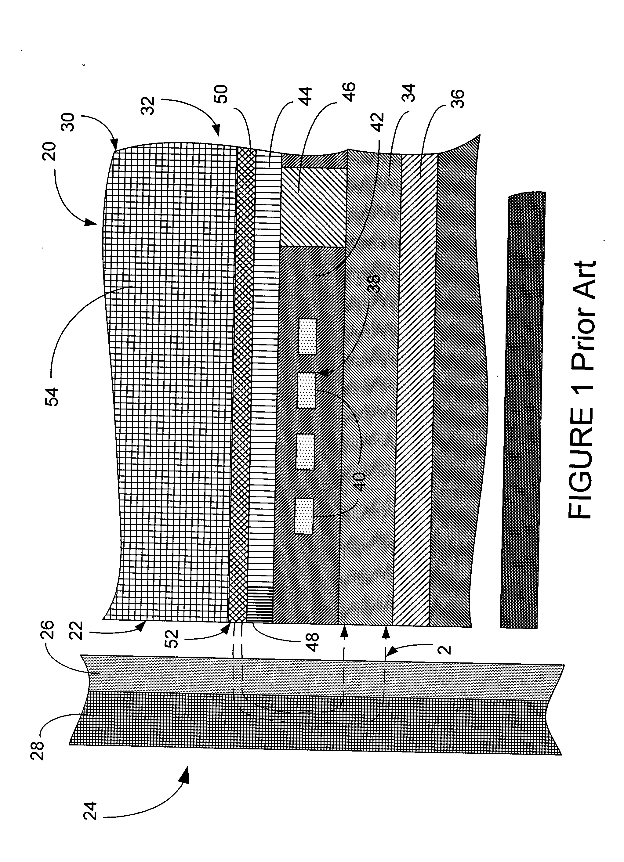
[0028]FIG. 1 (prior art) is a side cross-sectional diagram of the write head portion of a typical prior art perpendicular magnetic head. A slider 20 has an air bearing surface (ABS) 22 which flies above the surface of a hard disk 24. The disk 24 includes a high coercivity magnetic layer, also referred to the hard layer 26 that is fabricated on top of a magnetically soft layer 28.

[0029] The perpendicular head 30 typically includes a read head, which is not shown here. The write head portion includes a first magnetic pole P134 is fabricated upon an insulation layer 36. An induction coil structure 38, which includes coils 40, is fabricated upon the P1 pole 34. The coil turns 40 are typically formed within electrical insulation layers 42. A second magnetic pole layer, typically termed a P2 shaping layer 44, i...


PUM

PropertyMeasurementUnit
Angleaaaaaaaaaa
Angleaaaaaaaaaa
Electrical resistanceaaaaaaaaaa

Abstract

A method of fabrication of the write head of a perpendicular recording head allows for production of P3 pole tips of width less than 200 nm (200×10−9 meters). The method includes fabricating the P2 flux shaping layer, depositing the P3 layer, depositing a layer of ion-milling resistant material, depositing at least one sacrificial layer, shaping the P3 layer into P3 pole tip, removing the at least one sacrificial layer to leave the P3 pole tip, and encapsulating the P3 pole tip.

Description

BACKGROUND OF THE INVENTION [0001] 1. Field of the Invention [0002] The present invention relates to heads for high track density perpendicular magnetic recording, and more particularly relates to fabrication of poles of such heads. [0003] 2. Description of the Prior Art [0004] Data has been conventionally stored in a thin media layer adjacent to the surface of a hard drive disk in a longitudinal mode, i.e., with the magnetic field of bits of stored information oriented generally along the direction of a circular data track, either in the same or opposite direction as that with which the disk moves relative to the transducer. [0005] More recently, perpendicular magnetic recording systems have been developed for use in computer hard disk drives. A typical perpendicular recording head includes a trailing write pole, a leading return or opposing pole magnetically coupled to the write pole, and an electrically conductive magnetizing coil surrounding the write pole. In this type of disk ...

Claims


Application Information

Patent Timeline
IPC IPC(8): G11B5/33
CPCG11B5/33Y10T29/49043Y10T29/49041Y10T29/49046Y10T29/4906
Inventor BEDELL, DANIEL WAYNEHARRIS, TOM KING IIIKHERA, GAUTAM
Owner HITACHI GLOBAL STORAGE TECH NETHERLANDS BV
Why Eureka
Try Eureka