Method of removing casting defects

a casting defect and removal method technology, applied in the direction of blade accessories, crystal growth process, machine/engine, etc., can solve the problems of freckle formation, critical defects, and inability to meet the needs of casting, and achieve the effect of convenient and cost-effective manner

Inactive Publication Date: 2005-03-31
ANSALDO ENERGIA IP UK LTD
View PDF19 Cites 31 Cited by
  • Summary
  • Abstract
  • Description
  • Claims
  • Application Information

AI Technical Summary

Benefits of technology

[0014] One of the various aspects of the present invention is to provide a method for removing casting defects from an article with orien

Problems solved by technology

For example, too low of a thermal gradient across the solid/liquid interface, and/or too much of an incline of the interface compared to the horizontal, can result in the formation of freckles.
The chains can be anywhere from 2 mm to 20 cm long, and constitute zones of unacceptable weakness (fatigue strength) in single crystal alloys due to the lack of grain boundary strengtheners.
Freckles are also considered critical defects in columnar grain alloys, despite their higher content of grain boundary strengtheners.
Since it may comprise a high angle boundary which is almost always impossible to measure using Laue methods due to the limited width of the grain, slivers are also considered critical defects.
Other grain related linear defects include low angle grain boundaries which are above the allowed limit of misorientation.
Another well known potential defect in single crystal and columnar-grained castings is recrystallized grains.
Although these develop only during the solution heat treatment and/or reconditioning, repair, rejuvenation treatments, they can be considered casting defects since they are caused by excessive local deformation of the cast article due to the differential thermal contraction of the casting alloy, ceramic core and ceramic shell mold as the casting assembly cools.
Part cost decreases substantially when more parts can be cast at the same

Method used


Image

  • Method of removing casting defects
  • Method of removing casting defects
  • Method of removing casting defects

Examples


Embodiment Construction

[0034] Referring to the drawing figures, like reference numerals designate identical or corresponding elements throughout the several figures.

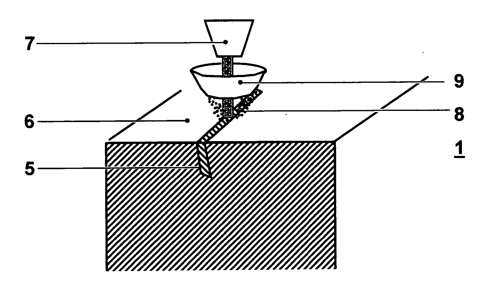
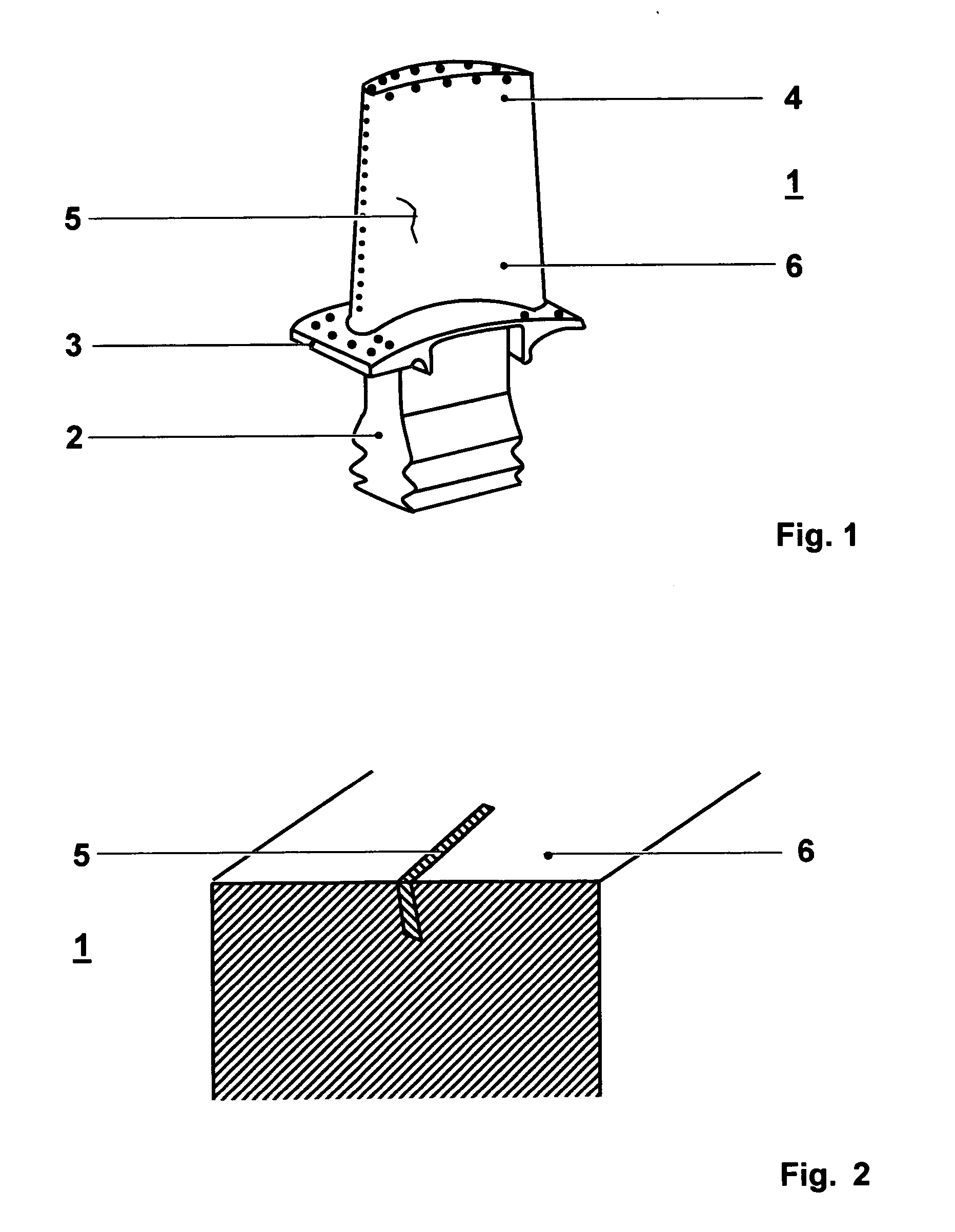
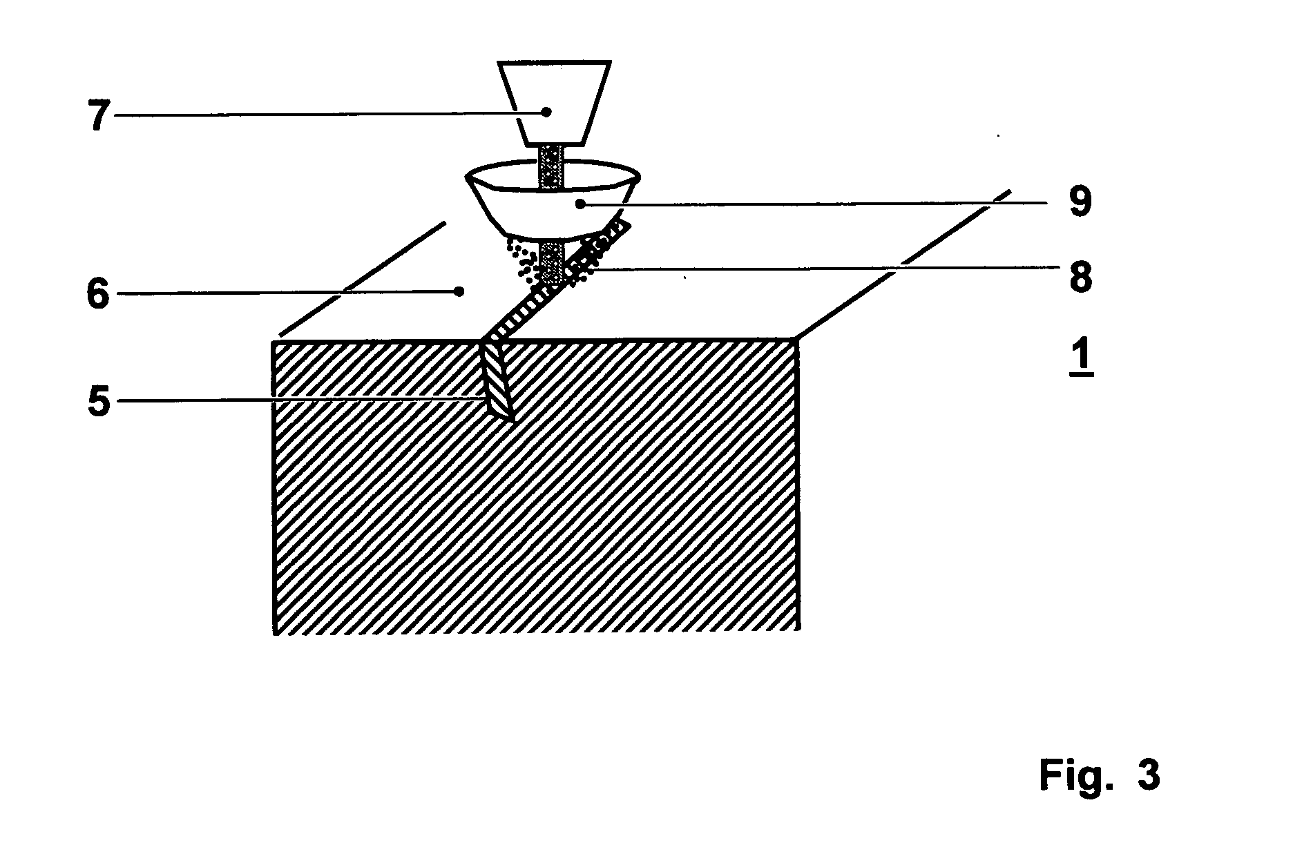
[0035]FIG. 1 shows a single crystal (SX) or directionally solidified (DS) article 1 such as blades or vanes of gas turbine engines, the gas turbine blade comprising a root portion 2, a platform 3 and a blade 4 and having a surface 6. The article can as an example be made from a nickel or cobalt based super alloy. Investment casting methods for producing such SX or DS articles are known e.g. from the prior art U.S. Pat. No. 4,96,501, U.S. Pat. No. 3,690,367 or EP-A1-0 749 790. As seen as well in FIG. 2, the article 1 exhibits a linear casting defect 5 such as a freckle, a sliver or any equiaxed or recrystallized grains of limited size somewhere after the production process. Non grain related linear defects include linear chains of pores, surface micro-cracks and dross or inclusions. FIGS. 3 and 4 show the different steps of removing the castin...


PUM

PropertyMeasurementUnit
Temperatureaaaaaaaaaa
Timeaaaaaaaaaa
Compositionaaaaaaaaaa

Abstract

A method for removing casting defects (5) from an article (1) with an oriented microstructure can include locating at least one casting defect (5) and melting the casting defect (5) locally by a heat source (7) to a depth at least as great as the casting defect (5) itself. The molten material can then be solidified epitaxially with respect to the surrounding oriented microstructure of the article (1) in a way that the resulting solidified area is substantially free of any defect.

Description

[0001] This application is a Continuation of, and claims priority under 35 U.S.C. § 120 to, International application number PCT / IB03 / 00362, filed 04 Feb. 2003, and claims priority under 35 U.S.C. § 119 to European application number 024 05 142.7, filed 27 Feb. 2002, the entireties of which are incorporated by reference herein.BACKGROUND OF THE INVENTION [0002] 1. Field of the Invention [0003] The invention relates to a method of removing casting defects in articles with oriented microstructure. [0004] 2. Brief Description of the Related Art [0005] Single crystal and directionally solidified castings, such as turbine blades, are manufactured using a directional solidification process in which a ceramic shell mould filled with an alloy in the liquid state is withdrawn from a heating zone (temperature above the melting point of the alloy) into a cooling zone (well below the melting point of the alloy in temperature). This is known for example from the documents U.S. Pat. No. 4,96,501,...

Claims


Application Information

Patent Timeline
IPC IPC(8): B22D19/10B22D27/04B23K31/02B23P6/04C30B11/00C30B13/00C30B33/00F01D5/00
CPCB22D19/10F05D2300/606B23K31/02B23K2201/001B23P6/007C30B11/00C30B13/00C30B33/00F01D5/005B22D27/045C30B29/52B23K2101/001
Inventor FERNIHOUGH, JOHNHOEBEL, MATTHIASKONTER, MAXIM
Owner ANSALDO ENERGIA IP UK LTD
Why Eureka
Try Eureka