Crack repair method

a technology of crack repair and cracking, which is applied in the direction of mechanical equipment, manufacturing tools, turbines, etc., can solve the problems of limited cracking within the components, creep deformation and oxidation, failure of the component in service, etc., and achieve the effect of rapid and inexpensive manner

Inactive Publication Date: 2005-03-31
ALSTOM TECH LTD
View PDF19 Cites 82 Cited by
  • Summary
  • Abstract
  • Description
  • Claims
  • Application Information

AI Technical Summary

Benefits of technology

[0011] The principle object of the invention is to provide means for repairing unfilled or partly filled cracks after a crack repair braze cycle in a more rapid and inexp...

Problems solved by technology

For example, turbine blades, vanes, combustors, burners, heat shields are all subject to large thermal gradients and high temperatures during engine operation, with each engine operating cycle giving rise to a new stress cycle in the component.
Although the materials chosen for the manufacture of these articles are normally high strength nickel based superalloys, the extreme loading cycles often give rise to limited cracking within the components during the normal allowed engine operating interval of the components.
In addition, the high temperatures give rise to creep deformation and oxidation.
In order to prepare the components for the next operation interval, the cracks must be repaired, otherwise they would continue to grow to unacceptable lengths possibly leading to failure of the component in service.
One known disadvantage of crack repair by welding is that many of the alloys currently used for gas turbine components contain high amounts of gamma...

Method used


Image

  • Crack repair method
  • Crack repair method
  • Crack repair method

Examples


Embodiment Construction

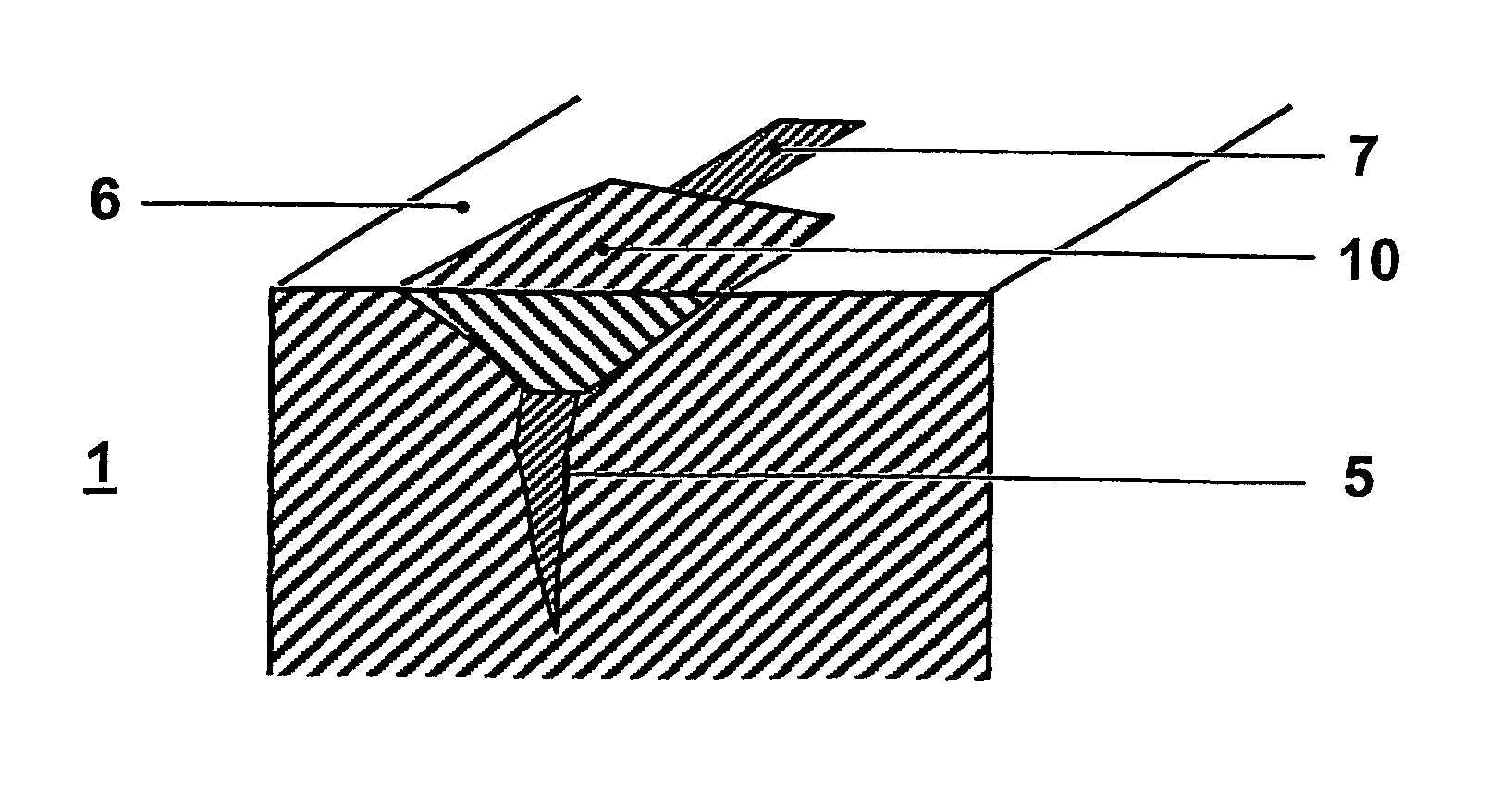
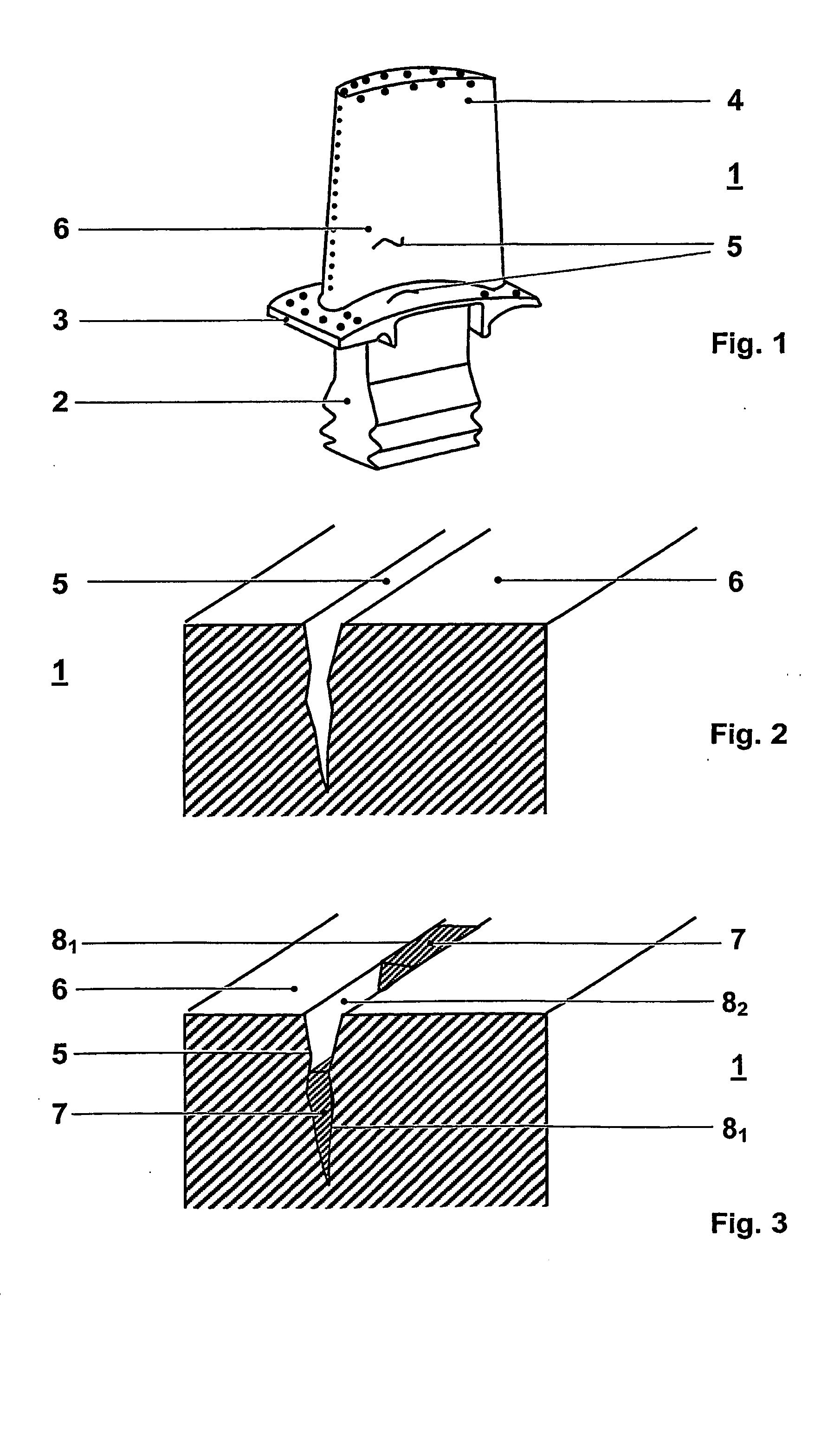
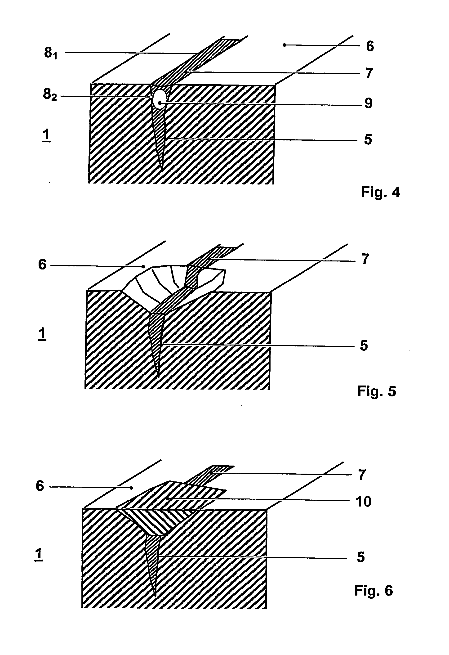
[0024]FIG. 1 shows a component 1 such as blades or vanes of gas turbine engines, the gas turbine blade comprising a root portion 2, a platform 3 and a blade 4. The component 1 exhibits cracks 5 somewhere on a surface 6 after being exposed to the hot gases of the gas turbine. FIGS. 2 to 6 show the different steps of repair operation according to the present invention.

[0025] As shown in detail and in way of an example in FIG. 2 the surface 6 of the component 1 exhibits a crack 5 which has to be repaired. The component 1 can be prepared for braze repair by cleaning of the surface using abrasive means such as grit blasting or grinding to remove at least a portion of the old coating or other debris, oxidation or corrosion products, or other contaminants, and by cleaning the cracks 5 using any means known in the state of the art such as Floride Ion Cleaning (FIC), other halide cleaning, hydrogen cleaning, salt bath cleaning, any combination thereof or other means. The crack 5 is subseque...


PUM

PropertyMeasurementUnit
Depthaaaaaaaaaa
Microstructureaaaaaaaaaa
Areaaaaaaaaaaa

Abstract

A method of repairing cracks on a surface of a component such as gas turbine components includes the steps of repairing the cracks of the component by brazing, detecting remaining cracks on the surface or below the surface, which were not properly filled with braze material during the repair brazing operation, and repairing the crack zones with a focussed low-heat input welding method using an appropriate weld filler materials.

Description

FIELD OF THE INVENTION [0001] The invention relates to a repair method of cracks on the surface of a component such as gas turbine articles. BACKGROUND OF THE INVENTION [0002] This invention relates to the repair of gas turbine components after being exposed to the conditions of engine operation. For example, turbine blades, vanes, combustors, burners, heat shields are all subject to large thermal gradients and high temperatures during engine operation, with each engine operating cycle giving rise to a new stress cycle in the component. This cyclic stressing at high temperature gives rise to the well known Low Cycle Fatigue and / or Thermal-Mechanical Fatigue modes of cracking in critical areas of high stress. [0003] Although the materials chosen for the manufacture of these articles are normally high strength nickel based superalloys, the extreme loading cycles often give rise to limited cracking within the components during the normal allowed engine operating interval of the compone...

Claims


Application Information

Patent Timeline
IPC IPC(8): B23K9/04B23K10/02B23K26/34B23P6/00
CPCB23K9/04B23K10/027B23K26/34B23K26/345B23P6/007B23P6/045B23K26/3213B23K2201/001B23K26/32B23K26/342B23K2101/001B23K2103/08B23K2103/26
Inventor BOEGLI, ANDREASFERNIHOUGH, JOHNULLMANN, OLIVER
Owner ALSTOM TECH LTD
Why Eureka
Try Eureka