Gradient coated stent and method of fabrication

a technology of stents and coatings, applied in the field of medical implants, can solve the problems of local tissue damage of certain drugs, significant re-narrowing of treated vessels, and dose of drugs delivered with time, and achieve the effect of reducing labor

Active Publication Date:
View PDF25 Cites 174 Cited by
  • Summary
  • Abstract
  • Description
  • Claims
  • Application Information

AI Technical Summary

Benefits of technology

[0018] Another aspect of the present invention provides a method of manufacture for a gradient coated stent avoiding dissolving subsequent layers.
[0021] Another aspect of the present invention provides a method of manufacture for a gradient coated stent reducing labor and allowing process automation.

Problems solved by technology

Soon after the procedure, however, a significant proportion of treated vessels re-narrow.
This causes problems with the dose of drug delivered with time.
This is called burst releasing and results in local tissue damage for certain drugs that are toxic in high doses.
This results in delivery of a less-than-effective dose.
With a uniform radial drug coating, stent designer must choose between a stent which risks initial tissue damage and a stent which has a limited effective drug lifetime.
A uniform drug coating may not provide the most effective therapy over time.
Immediately after stent implantation, inflammation and thrombosis occur due to the tissue trauma from the angioplasty and the presence of the stent.
A uniform, single drug coating is unable to treat both conditions.
There are also difficulties associated with manufacturing stents having multiple components or multiple layers.
Problems also arise during manufacture when the drugs, polymers, or solvents are incompatible.
For example, one solvent may be suitable for a particular drug, but unsuitable for a particular polymer.
The combination of a particular drug and a particular polymer may be incompatible and one or the other degrade when held in solution too long.
Incompatibility results in ineffective drugs or defective coatings.
Manufacturing techniques producing multiple coating layers with varying characteristics have been developed, but such methods increase the time and expense of manufacturing.
Poor surface preparation and layer incompatibilities can cause voids and defects at the boundaries between coating layers.

Method used


Image

  • Gradient coated stent and method of fabrication
  • Gradient coated stent and method of fabrication
  • Gradient coated stent and method of fabrication

Examples


Embodiment Construction

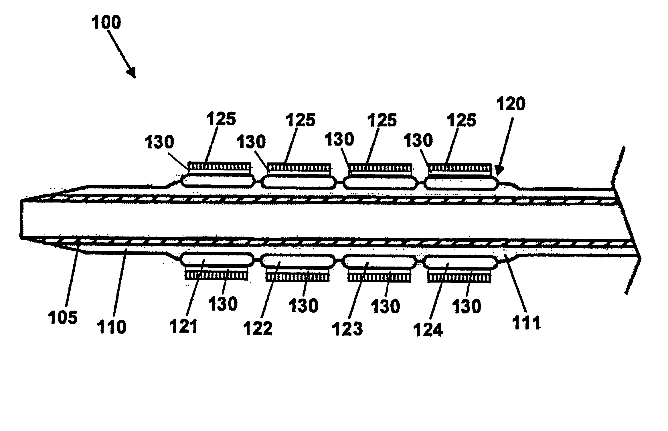
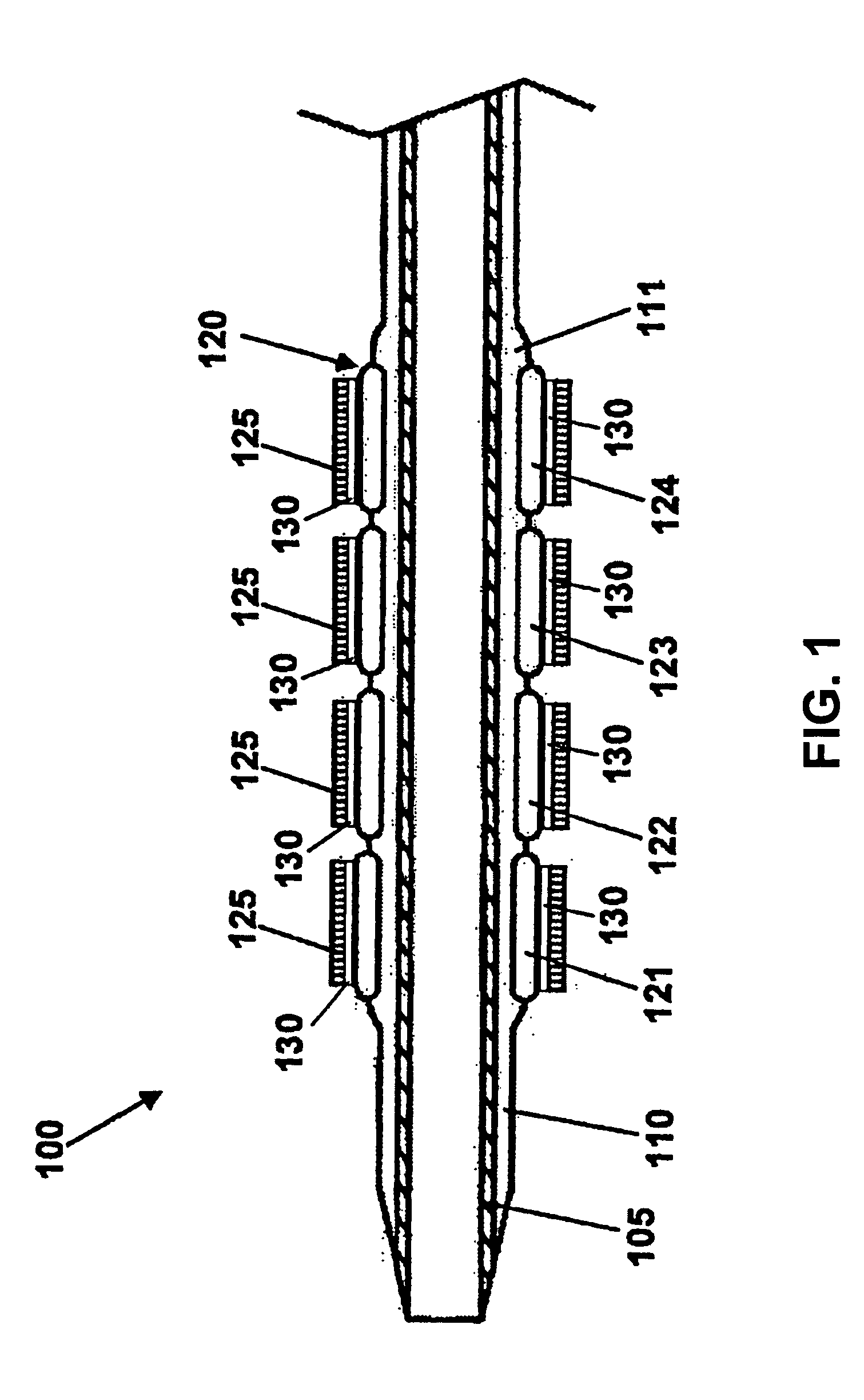
[0031]FIG. 1 shows a stent delivery system made in accordance with the present invention. The stent delivery system 100 includes a catheter 105, a balloon 110 operably attached to the catheter 105, and a stent 120 disposed on the balloon 110. The balloon 110, shown in a collapsed state, may be any variety of balloons capable of expanding the stent 120. The balloon 110 may be manufactured from a material such as polyethylene, polyethylene terephthalate (PET), nylon, Pebax® polyether-block co-polyamide polymers, or the like. In one embodiment, the balloon 110 may include retention means 111, such as mechanical or adhesive structures, for retaining the stent 120 on the balloon 110 until it is deployed. The catheter 105 may be any variety of balloon catheters, such as a PTCA (percutaneous transluminal coronary angioplasty) balloon catheter, capable of supporting a balloon during angioplasty.

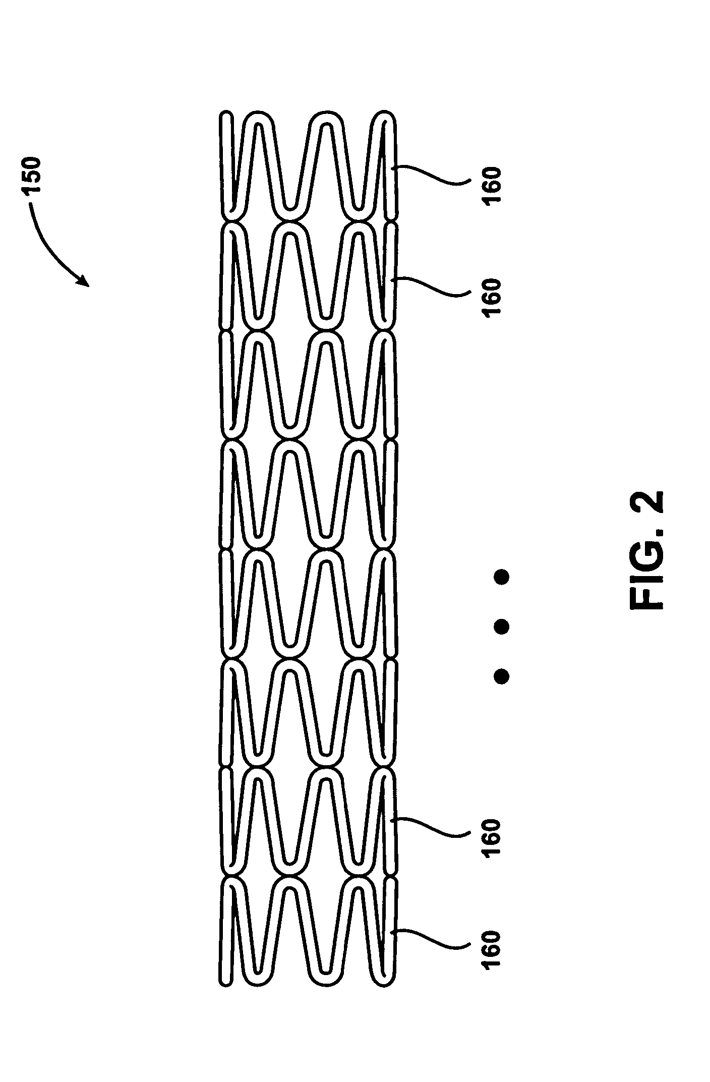
[0032] The stent 120 may be any variety of implantable prosthetic devices known in the art and c...


PUM

PropertyMeasurementUnit
thicknessaaaaaaaaaa
concentrationaaaaaaaaaa
solutionaaaaaaaaaa

Abstract

The gradient coated stent 150 of the present invention provides a coated stent having a continuous coating 130 disposed on the stent elements. The continuous coating 130 includes a first coating component and a second coating component. The concentration of the first coating component varies continuously over at least part of the thickness of the continuous coating 130. The concentration of the second coating component can also vary over at least part of the thickness of the continuous coating 130. In one embodiment, the concentration of the first coating component decreases in the direction from the stent element towards the outer edge of the continuous coating 130 and the concentration of the second coating component increases in the direction from the stent element towards the outer edge of the continuous coating 130.

Description

RELATED APPLICATIONS [0001] This application claims the benefit of U.S. Provisional Patent Application 60 / 505,675 filed Sep. 24, 2003.TECHNICAL FIELD [0002] The technical field of this disclosure is medical implant devices, particularly, a gradient coated stent and methods of making the same. BACKGROUND OF THE INVENTION [0003] Stents are generally cylindrical shaped devices that are radially expandable to hold open a segment of a blood vessel or other anatomical lumen after implantation into the body lumen. Stents have been developed with coatings to deliver drugs or other therapeutic agents. [0004] Stents are used in conjunction with balloon catheters in a variety of medical therapeutic applications including intravascular angioplasty. For example, a balloon catheter device is inflated during PTCA (percutaneous transluminal coronary angioplasty) to dilate a stenotic blood vessel. The stenosis may be the result of a lesion such as a plaque or thrombus. After inflation, the pressuriz...

Claims


Application Information

Patent Timeline
Patent Type & Authority Applications(United States)
IPC IPC(8): A61F2/00A61F2/02A61F2/90
CPCA61F2/0077A61F2/86A61F2/915A61F2/958A61F2002/072A61F2002/91541A61F2210/0004A61F2250/0067A61L31/10A61L31/16A61L2300/41A61L2300/416A61L2300/45A61L2300/606A61F2230/0054A61F2/91
Inventor CHENG, PEIWENTREMBLE, PATRICECARLYLE, WENDAJUDD, DIANEUDIPI, KISHORE
Why Eureka
Try Eureka