Method of producing a capacitor in a dielectric layer

a dielectric layer and capacitor technology, applied in the direction of capacitors, semiconductor devices, electrical equipment, etc., can solve the problems of reducing the absorption properties of anti-reflection coatings, reducing the capacitance of capacitors, and requiring separate lithographic and etching steps, so as to reduce the investment in apparatus and process technology necessary for producing capacitors, reduce the cost, and minimize the effect of outlay

Inactive Publication Date: 2005-04-14
INFINEON TECH AG
View PDF9 Cites 2 Cited by
  • Summary
  • Abstract
  • Description
  • Claims
  • Application Information

AI Technical Summary

Benefits of technology

[0017] Another advantage of the present invention is to be seen in the fact that, by planarizing the layer structure, the second conductive layer and, in addition, optionally the second dielectric layer and the first conductive layer can be structured laterally in a single method step. Hence, no further step is necessary for laterally structuring the layers, especially the upper capacitor plate, from the second conductive layer, whereby the investment in apparatus and process technology which is necessary for producing the capacitor will be reduced.
[0018] A further advantage resides in the fact that the method according to the present invention can be integrated with the production of via hole conductors so that it is e.g. possible to produce a via hole conductor in the first dielectric layer and the first conductive layer in a single step. Also the step of planarizing the layer structure can preferably be carried out in the same step in which the filling of the via holes is planarized. This will minimize the outlay for producing the capacitor.
[0019] Another advantage of the present invention is to be seen in the fact that the resultant well shape of the second dielectric layer and thus the lateral and vertical structural designs of the capacitor plates and electrodes, respectively,

Problems solved by technology

The resultant, manufacturing technology-dependent requirements on the robustness of the layers to be structured entail restrictions as far as the selection of the materials is concerned and necessitate minimum thicknesses of the layers.
In the case of a dielectric layer these requirements set undesired limits to an increase of the capacitance of the capacitor and vice versa to the reduction of the electrode area of the capacitor by the use of a thinner dielectric layer

Method used


Image

  • Method of producing a capacitor in a dielectric layer
  • Method of producing a capacitor in a dielectric layer
  • Method of producing a capacitor in a dielectric layer

Examples


first embodiment

[0050]FIG. 14 to 19 show in the form of schematic vertical sectional views various phases of a production method according to a further alternative embodiment of the present invention. This method differs from the first embodiment insofar as, after the production of conductors 12, 12a on the support layer 10, the first dielectric layer 20 is not produced homogeneously in one step, but spaces 140, 142, 144 between the conductors 12, 12a are first filled with a conformal HDP oxide (HDP=High Density Plasma silane oxide), i.e. an amount of HDP oxide is deposited which is just large enough to essentially fill the spaces 140, 142, 144 between the conductors 12, 12a. A characteristic feature of the HDP oxide is that it grows on all edges with the same thickness, i.e. its planarizing effect is only small. HDP oxide is therefore particularly suitable in the present case, since primarily the spaces 140, 142, 144 between the conductors 12, 12a are to be filled, whereas a planarizing effect is ...

seventh embodiment

[0069] One advantage of the method according to the present invention, which is shown on the basis of FIG. 26 to 30, is that it is also compatible with a very hard second dielectric layer 70 which cannot easily be removed and penetrated, respectively, in a polishing or planarizing step. On the other hand, the second dielectric layer 70 represents in this case a reliable stop layer for the second planarizing step.

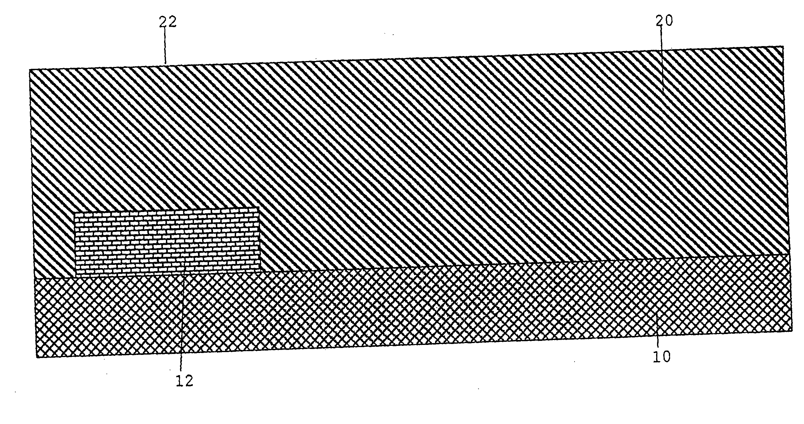
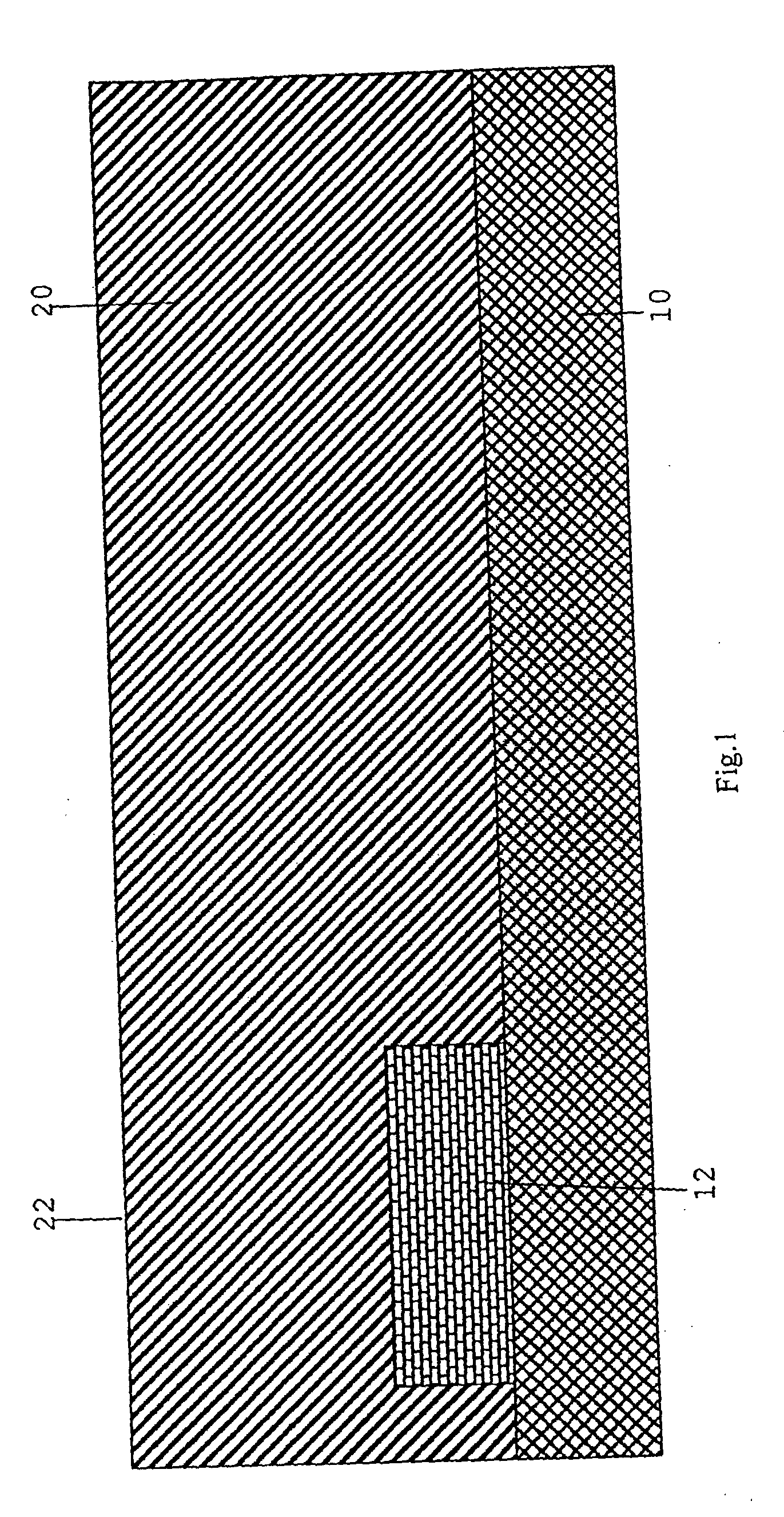
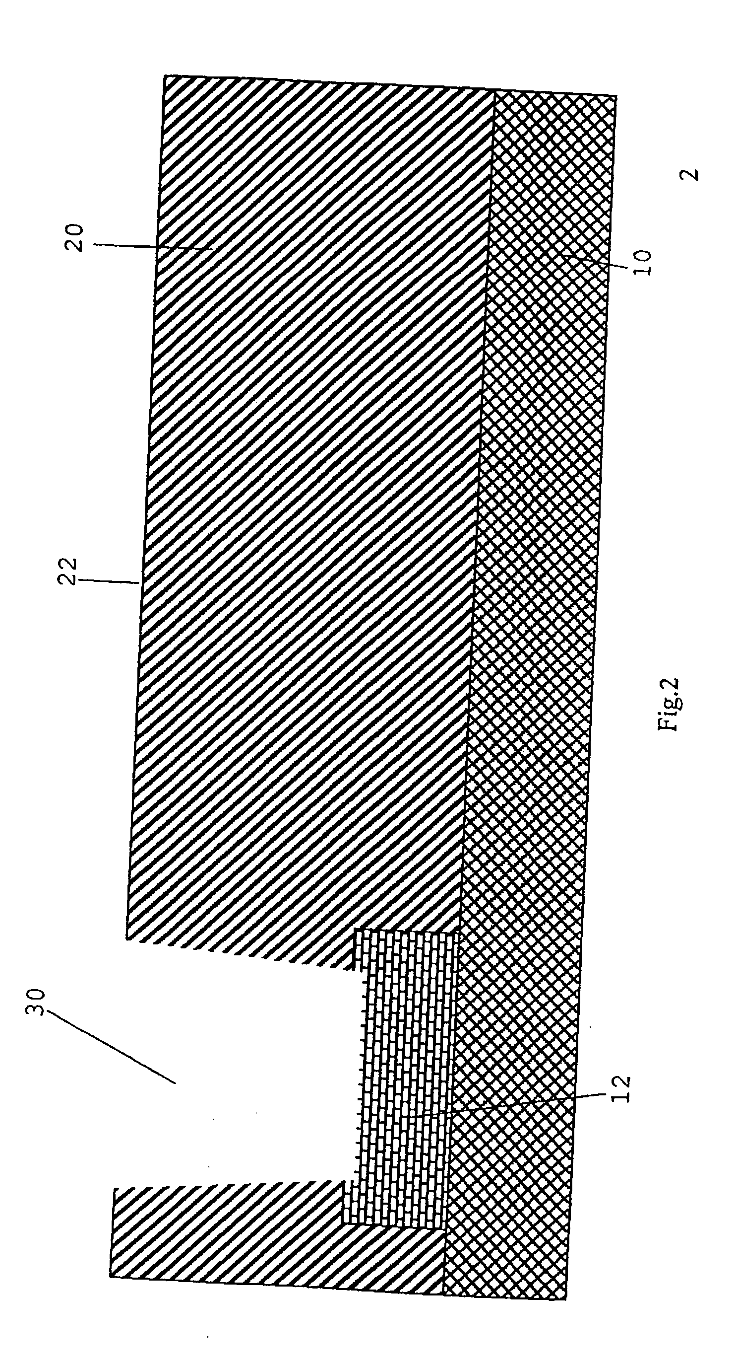
[0070] In all embodiments, the first dielectric layer 20 can be a first layer bordering directly on a component layer of a semiconductor structure, the support layer 10 representing the component layer and the via hole 30 reaching preferably directly down to a component in the component layer 10, i.e. down to a contact of the component, instead of reaching down to the conductor 12. However, the present invention may just as well be used for producing a capacitor in a dielectric layer 20 spaced from a component layer of a semiconductor structure; the first dielectric layer 20...


PUM


Abstract

In a method of producing a capacitor in a first dielectric layer, a recess is formed in a surface of the first dielectric layer. On the surface of the first dielectric layer and in the recess a first conductive layer is formed. On the first conductive layer a second dielectric layer is formed, the sum of a thickness of the first conductive layer and of a thickness of the second dielectric layer in the recess being smaller than a depth of said recess. A second conductive layer is formed on the second dielectric layer. The capacitor is obtained by planarizing the thus formed layer structure.

Description

CROSS-REFERENCE TO RELATED APPLICATION [0001] This application is a continuation of copending International Application No. PCT / EP03 / 00671, filed Jan. 23, 2003, which designated the United States and was not published in English, and is incorporated herein by reference in its entirety. BACKGROUND OF THE INVENTION [0002] 1. Field of the Invention [0003] The present invention relates to a method of producing a capacitor and, in particular, to a method of producing a capacitor which is suitable for integrating a capacitor in an intermediate dielectric between two wiring planes. [0004] 2. Description of Prior Art [0005] For producing capacitors in integrated circuits, a large number of techniques is known, the capacitance of a capacitor being determined by the surface of its electrodes, the distance at which these electrodes are located from one another and the permittivity ratio, i.e. the relative dielectric constant ∈r of a dielectric layer between the electrodes. In order to achieve ...

Claims


Application Information

Patent Timeline
IPC IPC(8): H01L21/02H01L21/321H01L21/3213H01L21/768H01L27/08
CPCH01L21/3212H01L21/32133H01L28/60H01L27/0805H01L28/55H01L21/76838
Inventor GOLLER, KLAUS
Owner INFINEON TECH AG
Why Eureka
Try Eureka