Eureka AIR delivers breakthrough ideas for toughest innovation challenges, trusted by R&D personnel around the world.

Electrochemical synthesis of ammonia

a technology of ammonia and electrochemical synthesis, which is applied in the direction of electrolysis process, electrolysis components, etc., can solve the problem of reducing the efficiency of the reaction

Inactive Publication Date: 2005-04-28
LYNNTECH
View PDF8 Cites 23 Cited by
  • Summary
  • Abstract
  • Description
  • Claims
  • Application Information

AI Technical Summary

Benefits of technology

[0018] Furthermore, the present invention provides an apparatus comprising a plurality of electrolytic cells and a bipolar plate separating each of the plurality of electrolytic cells. Accordingly, each of the plurality of electrolytic cells comprises a porous anode substrate in fluid communication with a source of hydrogen gas, a porous cathode substrate in fluid communication with a source of nitrogen gas, an electrolyte disposed within a matrix placed between the porous anode substrate and the porous cathode substrate, an anodic fluid flow field in electronic communication with the porous anode substrate opposite the matrix, and a cathodic fluid flow field in electronic communication with the porous cathode substrate opposite the matrix. Preferably, the anodic fluid flow field has a first face that is in electronic communication with the porous anode substrate and a second face in electronic communication with a first bipolar plate, and the cathodic fluid flow field has a first face that is in electronic communication with the porous cathode substrate and a second face in electronic communication with a second bipolar plate. The apparatus will typically further comprise hydrogen gas inlet and outlet manifolds for providing the fluid communication between the source of hydrogen gas and each of the porous anode substrates, and nitrogen gas inlet and outlet manifolds for providing the fluid communication between the source of nitrogen gas and each of the porous cathode- substrates. The hydrogen gas manifolds and the nitrogen gas manifolds are each selected from either an internal manifold or an external manifold. In a preferred embodiment, anodic cell frames and cathodic cell frames are disposed around the anode flowfields and cathode flowfields, respectively. These cell frames must be able to withstand the high temperatures, high pressures and harsh chemical environment of the molten salts. Accordingly, the cell frames may be made, for example, from graphite for process temperatures up to 500 Celsius, Inconel or Monel.
[0019] In one embodiment, the porous anode substrate and the porous cathode substrate are each selected from metal foams, metal grids, sintered metal particles, sintered metal fibers, and combinations thereof. Preferably, two or more of the metal components of the cell are metallurgically bonded together, such as by a process selected from welding, brazing, soldering, sintering, fusion bonding, vacuum bonding, and combinations thereof. For example, the anodic fluid flow field may be metallurgically bonded to the bipolar plate, the cathodic fluid flow field may be metallurgically bonded to the bipolar plate, the anodic fluid flow field may be metallurgically bonded to the porous anode substrate, the cathodic fluid flow field may be metallurgically bonded to the porous cathode substrate, and combinations thereof.

Problems solved by technology

However, the efficiency of the reaction is reduced by the high temperatures needed for the reaction to occur.

Method used

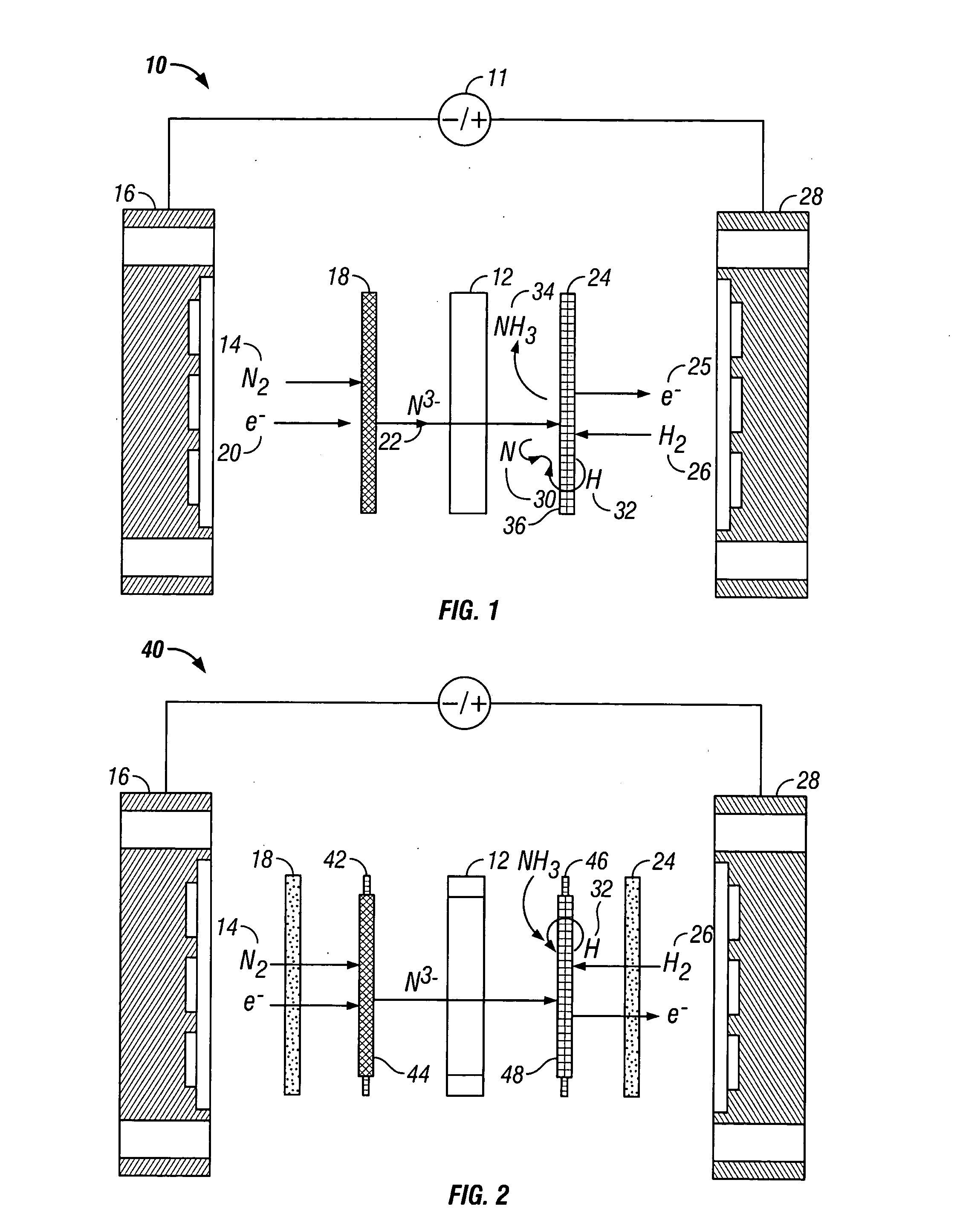
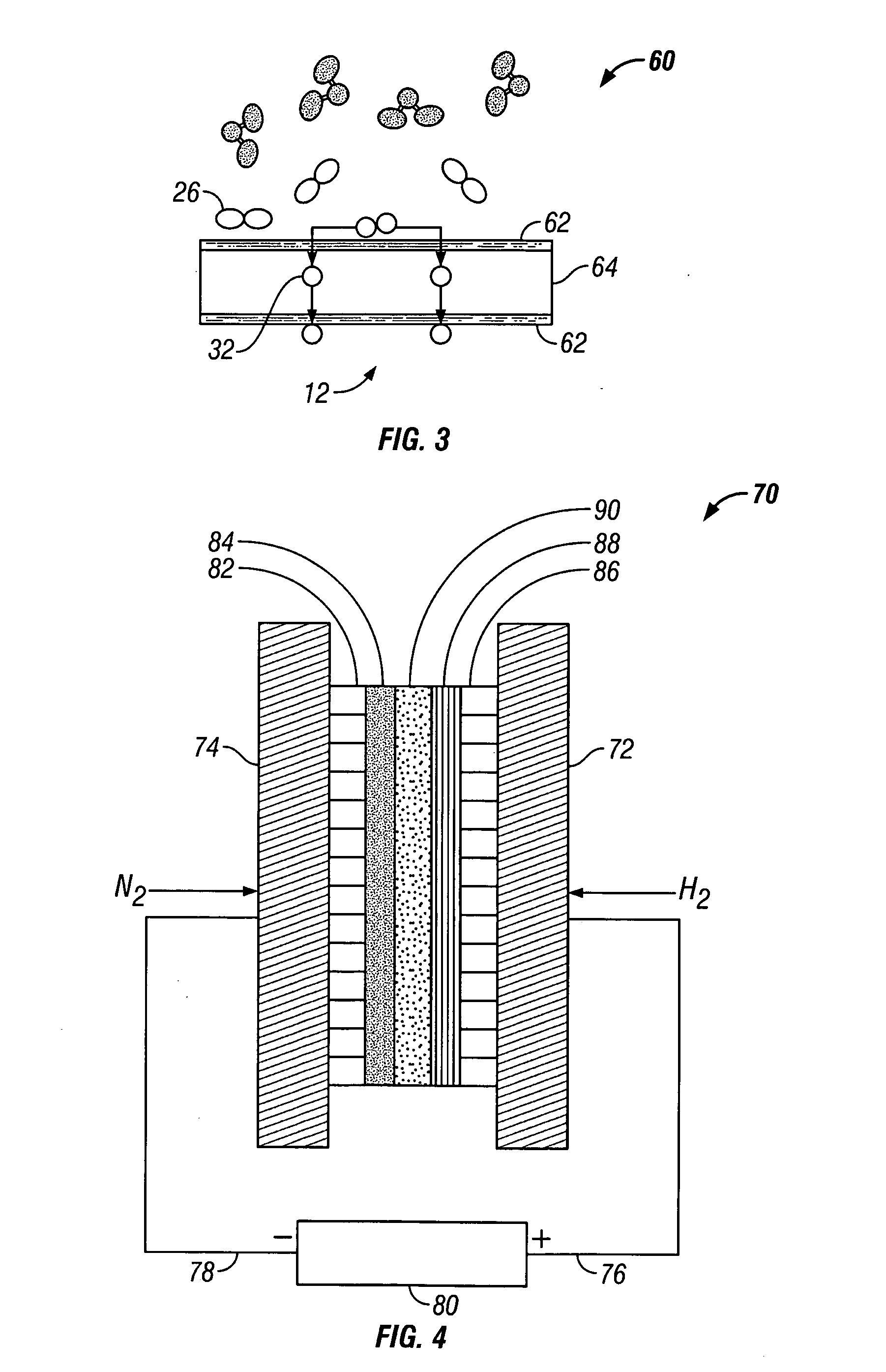

Image

  • Electrochemical synthesis of ammonia
  • Electrochemical synthesis of ammonia

Examples


example 1

[0056] Anhydrous lithium chloride and potassium chloride (Sigma Aldrich, St. Louis, Mo.) was vacuum dried for 48 hours at 140° C. After drying, the powders were removed from the vacuum oven and immediately placed into a vacuum dessicator before being transferred to a Vacuum Atmosphere Company dry box. An argon atmosphere was maintained at all times in the dry box, with oxygen and moisture concentrations below the detection limit of the sensors (1 ppm). A 59% LiCl / 41% KCL / 0.1% Li3N molar salt mixture was prepared by grinding the salts together with mortar and pestle, before transferring to a 100 ml high form alumina crucible (Fisher Scientific, Pittsburgh, Pa.).

[0057] All electrochemical measurements were performed versus a lithium / lithium ion reference electrode. The electrochemical cell was assembled in the glove box with the fuel cell type anode and cathode electrodes positioned with the active sides facing each other. The cathode was a sintered nickel gas diffusion electrode and...

example 2

[0068] An electrolyte salt mixture was prepared as described in Example 1 in a high form crucible. A fuel cell type cathode having a sintered nickel face was used along with an anode made from a titanium sheet attached to a nickel wire. Both electrodes were sealed into the reactor cap, placed into the powdered electrolyte salt. The reactor cap was then secured in position and sealed and an inert atmosphere was maintained. The reactor was then placed into a heater unit. Both electrodes were attached to a Tenmax Laboratory DC Power Supply Model No. 72-420. The nitrogen gas used to generate the nitride ion was dried using molecular sieves before it was flowed into the cell. Once a gas flow was established, the system was back pressured using a valve on the outlet line to prevent the molten salt from filling the internal cavity. Once the eutectic salt mixture reached the melting temperature a constant current of 0.1 Amp was applied for 45 minutes. As the reaction proceeded, the cell vol...


PUM

PropertyMeasurementUnit
porosityaaaaaaaaaa
porosityaaaaaaaaaa
thicknessaaaaaaaaaa

Abstract

A method for electrochemical synthesis of ammonia gas comprising providing an electrolyte between an anode and a cathode, providing hydrogen gas to the anode, oxidizing negatively charged nitrogen-containing species present in the electrolyte at the anode to form an adsorbed nitrogen species, and reacting the hydrogen with the adsorbed nitrogen species to form ammonia. Preferably, the hydrogen gas is provided to the anode by passing the hydrogen gas through a porous anode substrate. It is also preferred to produce the negatively charged nitrogen-containing species in the electrolyte by reducing nitrogen gas at the cathode. However, the negatively charged nitrogen-containing species may also be provided by supplying a nitrogen-containing salt, such as lithium nitride, into the molten salt electrolyte mixture in a sufficient amount to provide some or all of the nitrogen consumed in the production of ammonia.

Description

[0001] This application is a continuation of U.S. patent application Ser. No. 10 / 090,444, filed Mar. 4, 2002.BACKGROUND OF THE INVENTION [0002] 1. Field of the Invention [0003] This present invention relates to an electrochemical method and apparatus for the synthesis of ammonia. [0004] 2. Background to the Related Art [0005] Ammonia (NH3) is a colorless alkaline gas that is lighter than air and possesses a unique, penetrating odor. Since nitrogen is an essential element to plant growth, the value of nitrogen compounds as an ingredient of mineral fertilizers, was recognized as early as 1840. Until the early 1900's, the nitrogen source in farm soils was entirely derived from natural sources. Haber and Bosch pioneered the synthesis of ammonia directly from hydrogen and nitrogen on a commercial scale in 1913. Further developments in large-scale ammonia production for fertilizers have made a significant impact on increasing the world's food supply. [0006] Virtually every nitrogen atom o...

Claims


Application Information

Patent Timeline
Patent Type & Authority Applications(United States)
IPC IPC(8): C25B1/00
CPCC25B1/00
Inventor DENVIR, ADRIANMURPHY, OLIVER J.CISAR, ALANROBERTSON, PRISCILLAUSELTON, KYLE
Owner LYNNTECH
Why Eureka
Eureka Blog
Learn More