Electrolytic capacitor and electrolitic solution for driving electrolytic capacitor

a technology of electrolytic capacitor and electrolyte solution, which is applied in the direction of capacitors, electrolytes/absorbents, capacitors, etc., can solve the problems of large 40° c. impedance/20° c. impedance ratio, poor low temperature stability of aluminum electrolytic capacitors, etc., to achieve the effect of increasing the surface area and controlling capacitance, reducing the etching factor, and reducing the size of electrolytic capacitors

Inactive Publication Date: 2005-05-05
RUBYCON CORPORATION
View PDF7 Cites 23 Cited by
  • Summary
  • Abstract
  • Description
  • Claims
  • Application Information

AI Technical Summary

Benefits of technology

[0004] A valve metal is used as the electrode material for an electrolytic capacitor and, in an aluminum electrolytic capacitor, aluminum is used as the electrode material. The basic structure of an electrolytic capacitor comprises an element comprising electrodes of prescribed shape having a dielectric oxide film on the surface (etched, if necessary, to increase the surface area and control capacitance) as the anode and cathode, arranged in a mutually opposing manner, with an electrolyte solution-holding separator lying between them. The element of the electrolytic capacitor is sealed into a package. An electrolytic capacitor element may have a wound structure or a laminated structure.
[0005] In an electrolytic capacitor, such as that described above, the properties of the electrolyte solution constitute a major factor determining the performance of the electrolytic capacitor. Particularly, with the downsizing of electrolytic capacitors in recent years, anode foils or cathode foils with higher etching factors have been used and the resistivities of the capacitor have increased and, therefore, electrolyte solutions with lower resistivity and higher conductivity are required to be use in the electrolytic capacitor.
[0006] A conventional electrolytic capacitor electrolyte solution generally comprises a solution of a carboxylic acid, such as adipic acid or benzoic acid, or its ammonium salt as the electrolyte dissolved in a solvent composed of ethylene glycol (EG) as the main solvent with water added to about 15 wt %. Such electrolyte solutions have resistivities of about 1.5 Ω·m (150 Ω·cm).
[0007] On the other hand, the capacitor is required to have a low impedance (Z) for the purpose of achieving sufficient performance. The impedance is determined by several factors and, for example, it is lowered by increasing the electrode area of the capacitor and, therefore, large-sized capacitors inherently provide lower impedance. Improving the separator is another approach to lowering the impedance. However, the resistivity of the electrolyte solution is the major factor governing the impedance, especially in smaller capacitors.
[0008] Recently, low-resistivity electrolyte solutions have been developed using aprotic organic solvents such as GBL (y-butyrolactone). (See, for example, Japanese Unexamined Patent Publication SHO No. 62-145713, Japanese Unexamined Patent Publication SHO No. 62-145714 and Japanese Unexamined Patent Publication SHO No. 62-145715). However, capacitors using such aprotic electrolyte solutions have vastly inferior impedances compared to solid capacitors employing electron conductors with resistivity of 1.0 Ω·cm or below.
[0009] It is currently the situation that aluminum electrolytic capacitors, which employ electrolyte solutions, have poor low temperature stability and a rather large −40° C. impedance / 20° C. impedance ratio Z(−40° C.) / Z(20° C.) of about 40 at 100 kHz. In light of this situation, it has been desirable to provide an aluminum electrolytic capacitor with low impedance, low resistivity and excellent low temperature stability.

Problems solved by technology

However, capacitors using such aprotic electrolyte solutions have vastly inferior impedances compared to solid capacitors employing electron conductors with resistivity of 1.0 Ω·cm or below.
It is currently the situation that aluminum electrolytic capacitors, which employ electrolyte solutions, have poor low temperature stability and a rather large −40° C. impedance / 20° C. impedance ratio Z(−40° C.)
It therefore reacts with the anode foil or cathode foil to generate hydrogen gas, and this raises the pressure in the capacitor and increases the stress on the capacitor element, thereby causing deformation or breakage of the wound structure; this may promote fly out of the electrolyte solution to the exterior or activate the safety vent, thereby significantly altering the characteristics.
However, research by the present inventors has shown that although p-nitrophenol or o-nitroanisole exhibit an initial hydrogen gas absorbing effect in an electrolyte solution for use in an electrolytic capacitor with low water concentration, such as are commonly used in the prior art, they are unable to exhibit and maintain satisfactory hydrogen gas absorbing effects when the amount of water in the solvent of the electrolyte solution is 20 wt % or greater, or when the electrolytic capacitor is used for a prolonged period in a high-temperature environment.

Method used


Image

  • Electrolytic capacitor and electrolitic solution for driving electrolytic capacitor
  • Electrolytic capacitor and electrolitic solution for driving electrolytic capacitor

Examples


examples

[0056] The present invention will now be explained in greater detail through examples, with the understanding that these examples serve merely as illustrations of the invention and are in no way limitative.

[0057] The 30° C. resistivity values of the electrolyte solutions used in the examples were measured and are listed in the accompanying tables. The low-temperature (−40° C.) impedance and ordinary temperature (20° C.) impedance of the fabricated electrolytic capacitors were measured, and then the impedance ratio (Z ratio) as the ratio of the measured values was calculated for measurements at different frequencies (120 Hz and 100 kHz), as shown in the tables for each of the examples. In order to evaluate the usable life properties of each of the electrolytic capacitors, the initial values for the capacitance, tanδ and leakage current (values immediately after fabrication of each capacitor) and the change in those values after a high-temperature load test by standing for a prescrib...

examples 1-12

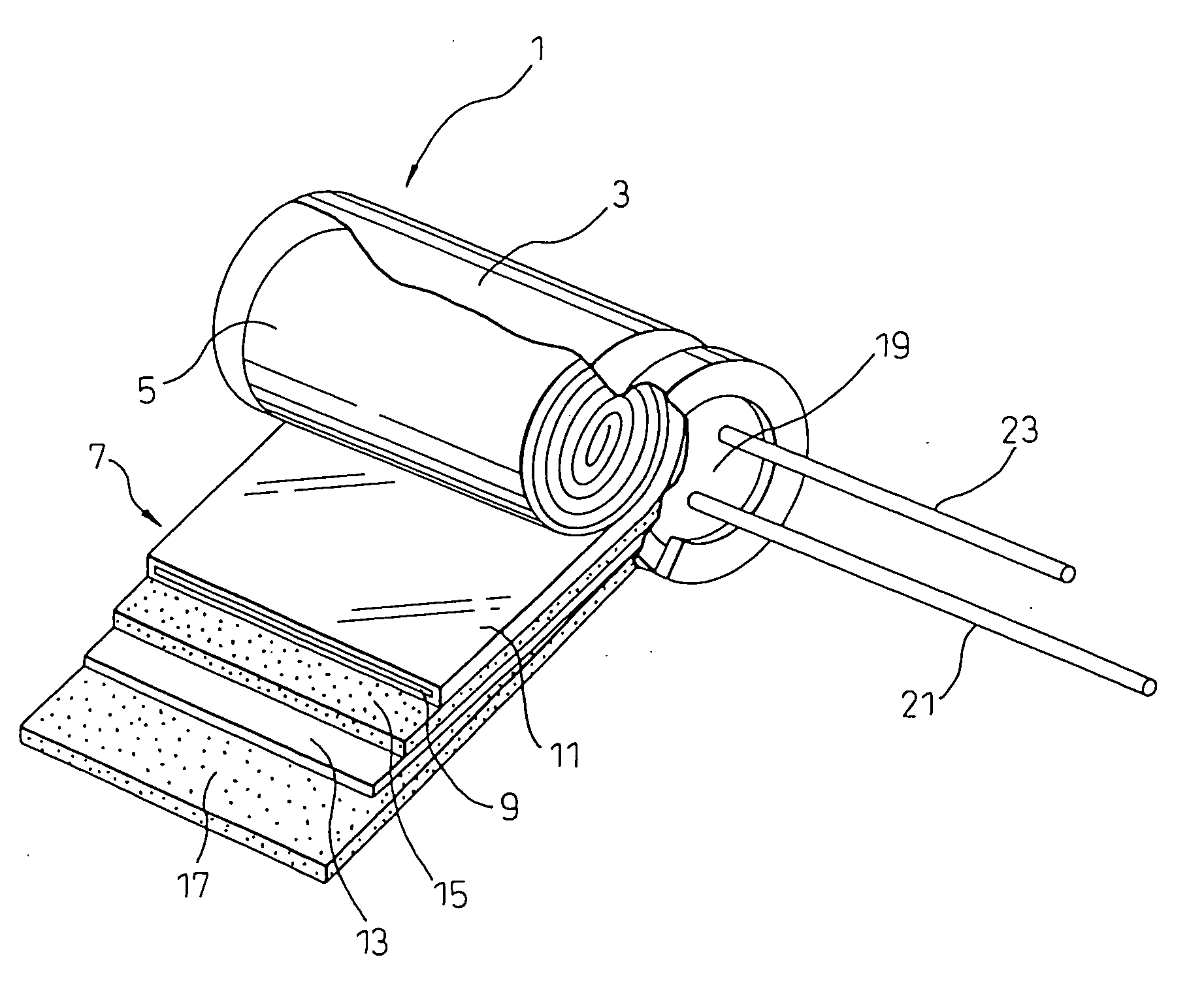
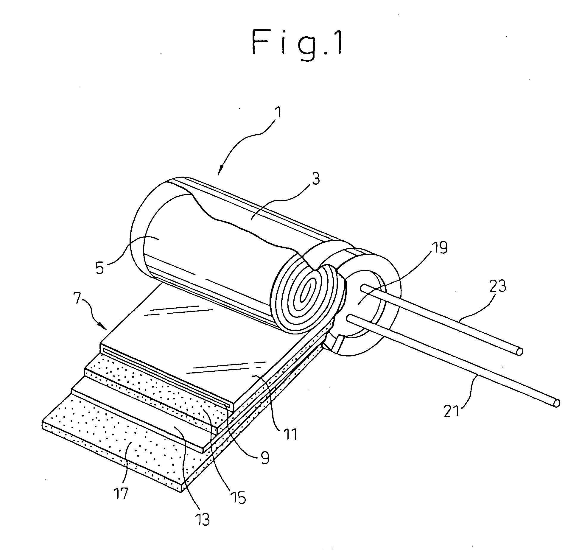
[0058] After impregnating a wound element of an electrolytic capacitor (10 WV-1000 μF) with an electrolyte solution having the composition shown in Table 1 below, it was placed in an aluminum case with the electrode drawing lead tab extending out of the case, and then the opening of the case was sealed with an elastic sealant to fabricate an electrolytic capacitor. Examples 1 to 10 were conducted to examine the effects of chelate compounds, saccharides, hydroxybenzyl alcohol, L-glutamic acid diacetate or its salt and gluconic acid and gluconic lactone. In Examples 11 and 12, there were fabricated capacitors under conditions with the compound having an unsaturated bond-containing chain electrode either coated onto the foils or adhered to the separator. The capacitors were subjected to characteristic testing, and the obtained results are summarized in Table 1 below.

examples 13-22

[0061] The procedure of Example 1 above was repeated, but in order to confirm the effects of simultaneously adding a nitro compound or nitroso compound with the chelate compounds, saccharides, hydroxybenzyl alcohol, L-glutamic acid diacetate or its salt or gluconic acid and gluconic lactone, the optional compositions added to the electrolyte solutions were varied for these examples as shown in Table 2. The test results are also summarized in Table 2.

TABLE 2SpecificZ ratioInitial valuesValues after 3000 hrs at 105° C.resistance120 Hz100 kHzLeakageLeakageAppear-Electrolyte solution30° C.[−40 / [−40 / CapacitancetanδcurrentCapacitancetanδcurrentancecomposition [wt %][Ω· cm]20° C.]20° C.][μF][%][μA][μF][%][μA](behavior)Exam-Ethylene glycol30.0201.14.610354.38.28955.62.7ple 13Water50.0Ammonium formate6.0Ammonium adipate5.0Phosphoric acid1.0Ethylenediamine-0.5tetraacetic acidNitrobenzoic acid1.0Ammonium hydrogen2.0maleateExam-Ethylene glycol40.0351.15.210345.17.99005.92.6ple 14Water40.0Ammo...


PUM


Abstract

The electrical properties and high-temperature characteristics of an electrolytic capacitor are rendered satisfactory by addition of a compound with an unsaturated bond-containing chain which serves to absorb hydrogen gas generated by reaction between the aluminum electrode foil and the electrolyte solution. The electrolytic capacitor contains the unsaturated compound which allows hydrogen addition, or the electrolytic solution, which comprises a solvent composed of 10-80 wt % of an organic solvent and 90-20 wt % water and at least one electrolyte selected from the group consisting of carboxylic acids or their salts and inorganic acids or their salts, also comprises one or more unsaturated compounds which are water-soluble or soluble in polar and protic polar solvents.

Description

FIELD OF THE INVENTION [0001] The present invention relates to an electrolytic capacitor, and more specifically, it relates to an electrolyte solution for use in an electrolytic capacitor and an electrolytic capacitor, particularly an aluminum electrolytic capacitor, having a low impedance and excellent low temperature stability, having a reduced pressure increase inside the capacitor, due to hydrogen gas generated in high-temperature environments, and having a satisfactory usable life. BACKGROUND OF THE INVENTION [0002] Capacitors are common electrical parts which are primarily used for power supply circuits or digital circuit noise filters in various types of electrical and electronic products. Capacitors are largely classified into electrolytic capacitors and non-electrolytic capacitors (ceramic capacitors, film capacitors, etc.). [0003] A wide variety of electrolytic capacitors are currently used, such as aluminum capacitors, wet tantalum electrolytic capacitors, and the like. B...

Claims


Application Information

Patent Timeline
Patent Type & Authority Applications(United States)
IPC IPC(8): H01G9/02H01G9/022H01G9/035
CPCH01G9/022H01G9/035
Inventor KOMATSU, AKIHITOIIDA, TOSHIKAZUNOZAWA, TAKASHIMATSUZAWA, TAKETOOGAWARA, TETSUSHI
Owner RUBYCON CORPORATION
Why Eureka
Try Eureka