Supercharge Your Innovation With Domain-Expert AI Agents!

Process for the production of a thermal shock tube, and the product thereof

Inactive Publication Date: 2005-05-26
IBQ IND QUIMICAS
View PDF6 Cites 10 Cited by
  • Summary
  • Abstract
  • Description
  • Claims
  • Application Information

AI Technical Summary

Benefits of technology

[0041] The present invention is a thermal shock tube and the method of manufacturing the shock tube. The shock tube is used as a signal transmission device for connecting and initiating explosive columns, or as a flame conductor. The device is usually complemented by a delay element, or it can be used as a delay unit. The shock tube uses a pyrotechnic mixture with low sensitivity to ignition by shock or friction, with low toxicity, which generates a spark with superior thermal performance. The manufacturing process utilizes continuous and separated dosing of the individual non-active components, in conjunction with the formation of the plastic tube, making the process safer and yielding a more accurate dosing. The resultant product maintains the advantages of current art pyrotechnic shock tubes relative to the shock wave propagating tube, i.e. larger transmission sensibility and sensitivity, propagation even with cuts or holes in the tubes, and low risk transport classification. The shock tube of the present invention gives the following additional advantages: use of low toxicity components, use of ordinary, low cost, low adhesiveness polymers, generation of a spark that propagates through knots, closed kinks or tube obstructions, and resistance to failure by attack of components of hot explosive emulsions.
[0042] The focus of the present invention is to obtain desirable characteristics in the polymers that form the tube, but not to optimize the pyrotechnic mixtures formulation, in order to use ordinary, low cost polymers. The new approach is also multipurpose, i.e., to obtain the greatest possible number of desirable characteristics through the formulation of the pyrotechnic mixture. The process and product from this invention have the following advantages over the current art shock tubes:
[0043] The thermal shock tube employs an optimized pyrotechnic mixture with low toxicity.

Problems solved by technology

This product was an improvement over the original NONEL tube, as SURLYN alone is expensive and has a low resistance to external damage.
However, the best conventional shock tubes continue to be made in two layers, and the inner layer continues to be SURLYN, as even a low dislodgement of poorly adhered explosive powder may lead to failures in signal propagation due to discontinuities in the powder layer or by concentration of loose powder in the lower parts of the tube during field application.
Hot diesel fuel is particularly aggressive to LLDPE, and prolonged contact of the tube with hot, diesel fuel-based emulsions causes failure in signal propagation.
The PVA protective skin is fragile and does not adhere well to the LLDPE, and so a pretreatment with a cleaner (like chromic acid), with hot air or with an adhesion promoter (like Vinamul EVA copolymer) is necessary.
There was therefore no attempt by the inventor to optimize the thermal action of a spark, nor to eliminate toxic components, nor to guarantee the crossing through restrictions in the tube.
It is evident, by the patent's descriptive report, and from all of the examples, that its use as a delay element is limited to the range of tens of milliseconds, which is not adequate for most of the delays required in field practice.
a) The production of the tube loaded with explosives (RDX, HMX or PETN are toxic and dangerous) offers risks both of accidental explosions and in the handling toxic products, requiring special care and protection in the production line.
The fact that molecular explosives are used impedes the dosing of non-active components during the extrusion of the tube.
b) In the conventional shock tube, the reaction products are basically hot gases which, when leaving the final extremity of the tube, expand with loss of heat, such heat loss inhibiting the ignition of the pyrotechnic delay mixture.
Slower delay powders are particularly insensitive to the shock tube output.
As a consequence, the final product has greater production costs, and the processing and handling of the pyrotechnic mixture entails significant accidental ignition risks.
d) Conventional shock tube loading lacks sufficient critical mass and critical diameter to properly propagate a shock wave by classical detonation theory.
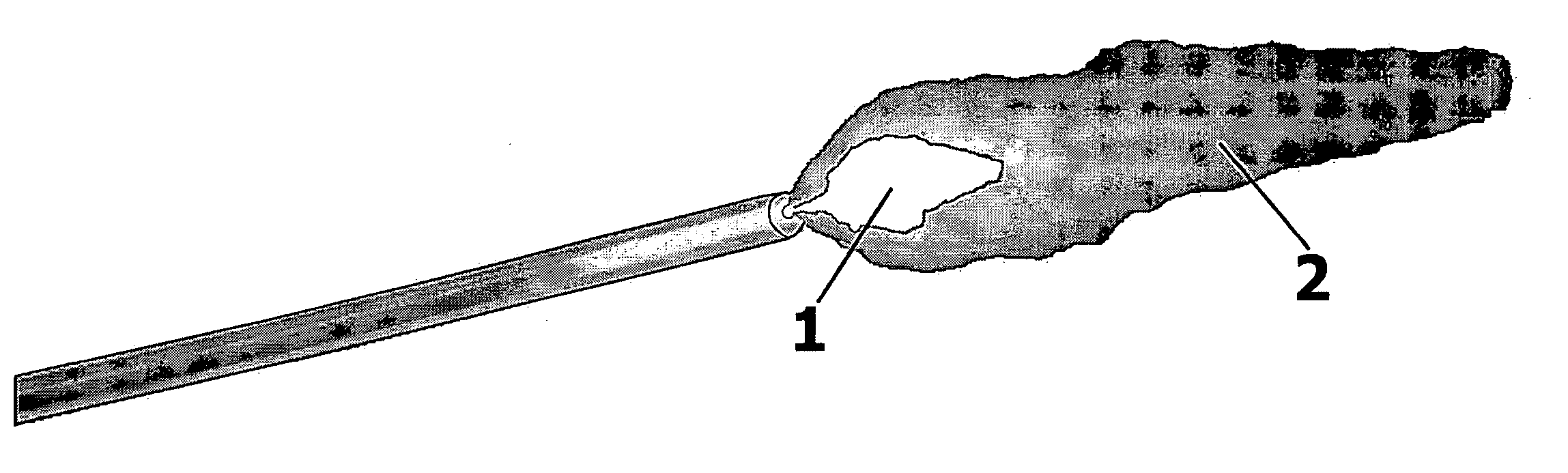
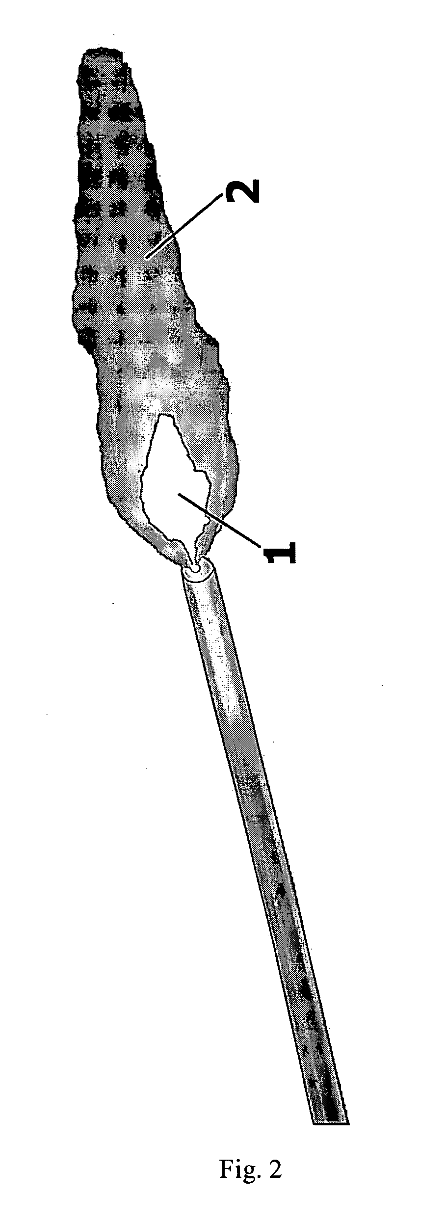
Due to this feature, a conventional shock tube fails if there is a cut or a close restriction in the inner duct, dispersing the shock wave.
In field practice, if unexpected cuts, stretching, knots, holes, or closed kinks unexpectedly appear in the tube, the tube can fail to propagate.
f) Conventional shock tubes are classified for transport purposes as an explosive in many countries, which results in additional costs and difficulties for transportation, especially after the increase in dangerous products regulations resulting from the fight against terrorism.
This improved process still includes the use of expensive SURLYN.
i) Conventional explosive powders lack sufficient activation energy to propagate in case of contamination of the tube interior by hot hydrocarbons (most likely diesel fuel) from explosive emulsions.
Polymers, including LLDPE, are quite susceptible to aggression.
Minor quantities of adherence-improving additives, typically EVA copolymers, are even more subject to attack by volatile fractions of diesel fuel.
An additional skin of hydrophilic polymer like PVA is needed, but abrasion resistance of the skin, particularly in the rough environmental conditions found in field practice, is remarkably bad, causing removal of the skin and failures of the tube.
This relatively broad range interferes with the accuracy of the delay element timing.
However, the timing error of a certain length of tube is added to the intrinsic timing error of the electronic circuit.
Highly flame-sensitive mixtures are usually also highly sensitive to mechanical shock, friction and electrostatic discharge, increasing the risks of accidental detonation.
The additional element also increases the manufacturing costs.
A) Pyrotechnic mixtures use toxic components (K2Cr2O7, Sb2O3, Sb2O5) and flammable solvents, demanding recycling of the solvents, and creating handling issues and requiring appropriate waste disposal.
B) The process of extrusion of the plastic tube includes the dosing of a previously prepared sensitive pyrotechnic mixture during the formation of the plastic tube, with safety risks in handling and processing.
C) Like a conventional shock tube, a pyrotechnic shock tube does not resist aggression from the hydrocarbons present in emulsion explosives, and prolonged exposure leads to failures in propagation.
D) Mixtures of O2+Al or Mg were not shown to be feasible in practice, due to the loss of gases in the production and use of the product.
E) Mixtures of Fe2O3+Al or Mg were also not shown to be feasible in practice, due to the low sensibility of these pyrotechnic mixture to the ignition stimulus of blasting caps and a high rate of propagation failures.
I) Pyrotechnic mixtures are not optimized to allow propagation through closed knots, cuts or kinks.
Aa) As with the original pyrotechnic shock tube, the process also includes the dosing of a previously prepared sensitive pyrotechnic mixture, during the formation of the plastic tube, with safety risks in handling and processing.
Bb) The system makes use of direct tube-to-tube connections for supplying a time delay exclusively through a predetermined length of tube, and is limited to fast delays, in the range of tens of milliseconds, while field blasting operations demand delay timing up to 10 s.
A low speed mixture lacks the energy to directly ignite slower, low sensitive delay mixtures, and to propagate through close kinks, knots or cuts.

Method used


Image

  • Process for the production of a thermal shock tube, and the product thereof
  • Process for the production of a thermal shock tube, and the product thereof
  • Process for the production of a thermal shock tube, and the product thereof

Examples


Embodiment Construction

[0063] One of the fundamental concepts for the understanding of the present invention was described by the Russian chemist Tammann. According to his theory, the vibrational energy needed to start an oxidation-reduction reaction among solid substances is largely available at the temperature equivalent to half the melting point of the substance, in the absolute scale (K). This temperature of Tammann explains why certain components make pyrotechnic mixtures quite sensitive to heat to flame and mechanical shock, while other ones are quite difficult to start an propagate. For example, mixtures of powdered aluminum, whose temperature of Tammann is 193° C. and ferrous-ferric oxide, Fe3O4, whose temperature of Tammann is 632° C. are particularly difficult to start and propagate, while mixtures of powdered aluminum and potassium chlorate, whose temperature of Tammann is only 47.5° C., is especially dangerous. One of the invention objectives is to obtain enough activation energy to ensure the...


PUM


Abstract

A process for the production of a thermal shock tube is used to form a product that is utilized as a transmission device for connecting and initiating explosive columns, or as a flame conductor. The device is usually complemented by a delay element or used as a delay unit. The thermal shock tube uses a pyrotechnic mixture with low sensitivity to ignition by shock or friction, with low toxicity, and which generates a spark with superior thermal performance. The process utilizes continuous and separated dosing of the individual non-active components, in conjunction with the formation of the plastic tube, making the process safer, and with a more accurate dosing. The product maintains the advantages of current art pyrotechnic shock tubes relative to the shock wave propagating tube, e.g. larger transmission sensibility and sensitivity, propagation even with cuts or holes in the tubes, and low risk transport classification. The product has the additional advantages of using low toxicity components, use of ordinary, low cost, low adhesiveness polymers, the generation of a spark that propagates through knots, closed kinks or tube obstructions, and resistance to failure due to attack of components by hot explosive emulsions.

Description

BACKGROUND OF THE INVENTION [0001] 1. Field of the Invention [0002] The present invention relates generally to explosive signal transmission devices, and more particularly is a thermal shock tube and the method of manufacturing the shock tube. [0003] 2. Description of the Prior Art [0004] Since at least the 1970's, low energy signal fuses known commercially as “non-electric detonators” or “shock tubes”, have been widely used for connecting and initiating explosive charges in the mining and quarrying industries. Such devices, marketed with brands like NONEL, EXEL, BRINEL, etc., came to be substituted for electric blasting caps ignited by metallic wiring, and represented a revolution in the market of detonation accessories, due to the ease of connection and application, and to the intrinsic safety against accidental ignition by induction of spurious electric current. [0005] Current processes and products that use high explosives as components (hereinafter referred to as “conventional ...

Claims


Application Information

Patent Timeline
IPC IPC(8): C06B33/12C06C5/04
CPCC06C5/04C06B33/12
Inventor FALQUETE, MARCO ANTONIO
Owner IBQ IND QUIMICAS
Features
  • R&D
  • Intellectual Property
  • Life Sciences
  • Materials
  • Tech Scout
  • Unparalleled Data Quality
  • Higher Quality Content
  • 60% Fewer Hallucinations
Learn More