
Maximum extended load line limit analysis for a boiling water nuclear reactor

a nuclear reactor and maximum extended load technology, applied in the field of nuclear reactors, can solve the problems of reducing flexibility during startup and at full power, and achieve the effects of reducing fuel cycle costs, increasing operating flexibility, and increasing core flow rang

Inactive Publication Date: 2005-06-02
GENERAL ELECTRIC CO
View PDF9 Cites 6 Cited by
  • Summary
  • Abstract
  • Description
  • Claims
  • Application Information

AI Technical Summary

Benefits of technology

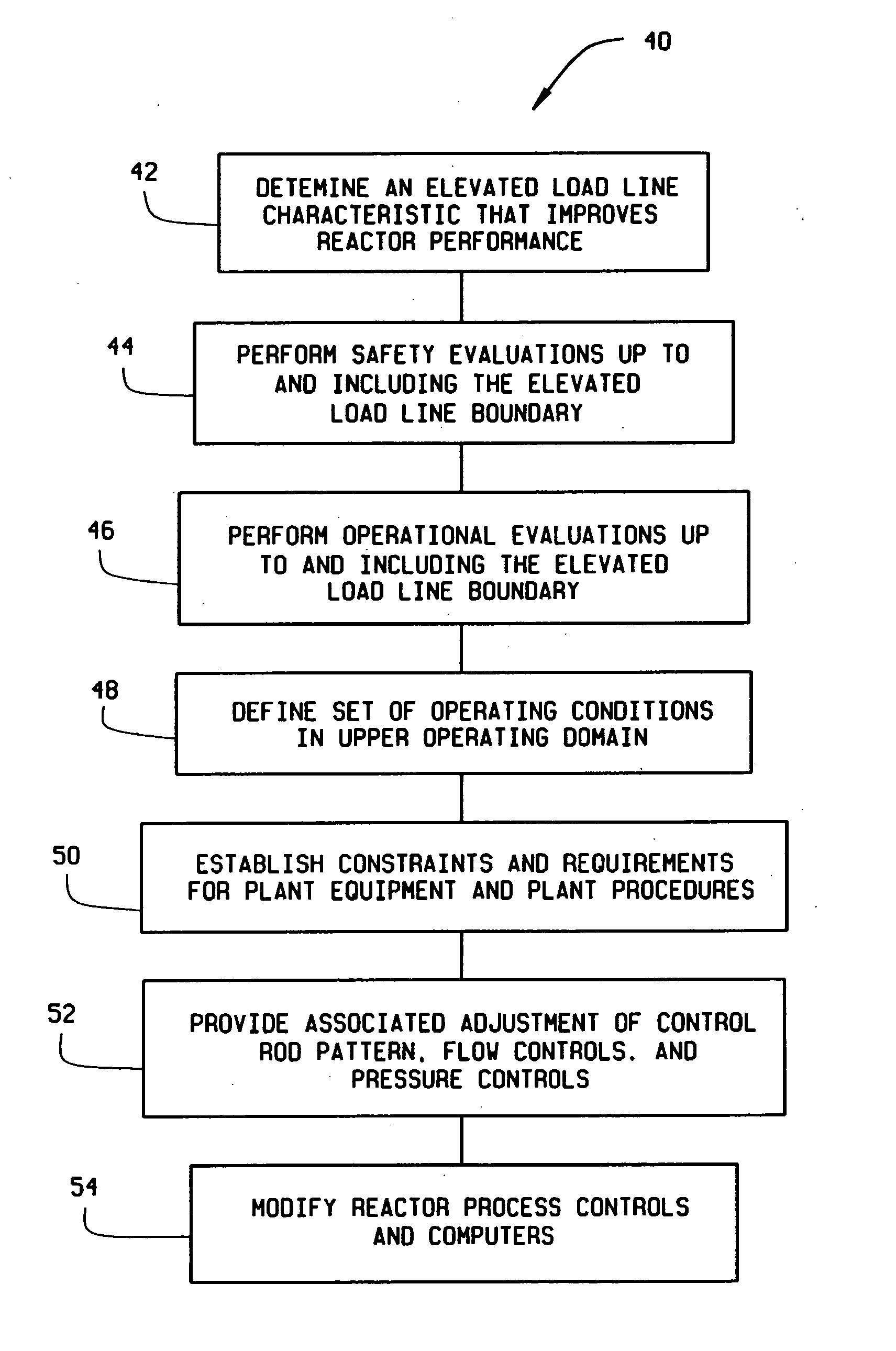
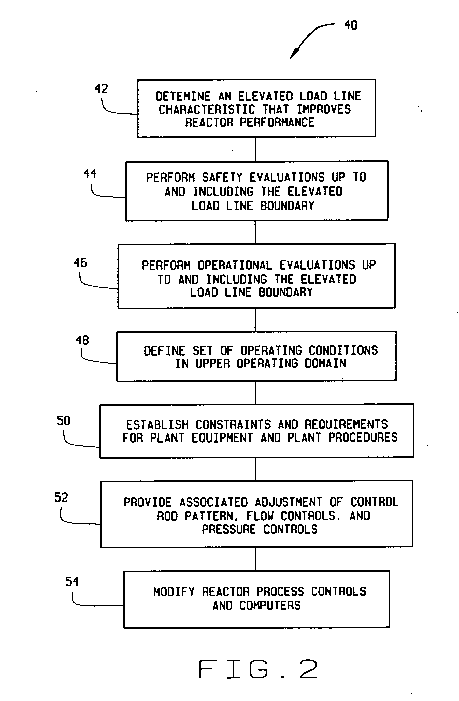
[0008] The method for expanding the operating domain of a boiling water nuclear reactor includes, in one embodiment, determining an elevated load line characteristic that improves reactor performance, performing safety evaluations at the elevated load line to determine compliance with safety design parameters, and performing operational evaluations up to the elevated load line. The method also includes defining a set of operating conditions for the reactor in an upper operating domain characterized by the elevated load line.
[0011] The above described method provides analyzed limits that permit full power operation of the reactor at a core flow lower than 75 percent of rated core flow, which currently is the lowest permitted core flow for license approval. The lower than 75 percent core flow permits operation of the reactor over a larger core flow range and operating flexibility during startup and at full power. The method further provides savings in fuel cycle costs and faster plant startups due to the increased ability to establish desired full power control rod pattern at partial power conditions.
[0012] The method still further provides a reduced cycle average recirculation pumping power consumption resulting in an increase in net station output.

Problems solved by technology

This upper boundary line constrains operation at the uprated power to a significantly smaller range of core flow and reduces flexibility during startup and at full power.

Method used


Image

  • Maximum extended load line limit analysis for a boiling water nuclear reactor
  • Maximum extended load line limit analysis for a boiling water nuclear reactor
  • Maximum extended load line limit analysis for a boiling water nuclear reactor

Examples


Embodiment Construction

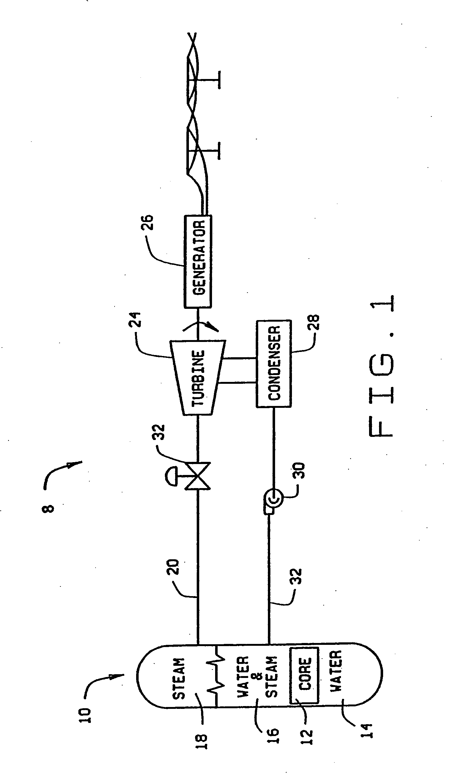
[0017]FIG. 1 is a schematic diagram of the basic components of a power generating system 8. The system includes a boiling water nuclear reactor 10 which contains a reactor core 12. Water 14 is boiled using the thermal power of reactor core 12, passing through a water-steam phase 16 to become steam 18. Steam 18 flows through piping in a steam flow path 20 to a turbine flow control valve 22 which controls the amount of steam 18 entering steam turbine 24. Steam 18 is used to drive turbine 24 which in turn drives electric generator 26 creating electric power. Steam 18 flows to a condenser 28 where it is converted back to water 14. Water 14 is pumped by feedwater pump 30 through piping in a feedwater path 32 back to reactor 10.

[0018]FIG. 2 is a flow chart of a method 40 for expanding the operating domain of boiling water nuclear reactor 10. In one aspect, method 40 is applicable to boiling water nuclear reactor plants which can operate at higher than the original rated thermal power, wh...


PUM


Abstract

A method for expanding the operating domain of a boiling water nuclear reactor that permits safe operation of the reactor at low core flows is described. The operating domain is characterized by a map of the reactor thermal power and core flow. In an exemplary embodiment, the method for expanding the operating domain of a boiling water nuclear reactor permits operation of the reactor between about 120 percent of rated thermal power and about 85 percent of rated core flow to about 100 percent of rated thermal power and about 55 percent of rated core flow. The method includes determining an elevated load line characteristic that improves reactor performance, performing safety evaluations at the elevated load line to determine compliance with safety design parameters, and performing operational evaluations at the elevated load line. The method also includes defining a set of operating conditions for the reactor in an upper operating domain characterized by the elevated load line. Additionally, the method includes performing a detailed analysis of the performance of the core recirculation system and the system control components. further, the method provides for modifying the reactor process controls and computers to permit the reactor to operate in the expanded operating domain within predetermined safety parameters. Also, safety mitigation action setpoints are adjusted to permit reactor operation in the expanded operating domain.

Description

BACKGROUND OF THE INVENTION [0001] This invention relates generally to nuclear reactors and more particularly to a design analysis method that permits operation of a boiling water nuclear reactor in an expanded region of the power / core flow map. [0002] A typical boiling water reactor (BWR) includes a pressure vessel containing a nuclear fuel core immersed in circulating coolant, i.e., water, which removes heat from the nuclear fuel. The water is boiled to generate steam for driving a steam turbine-generator for generating electric power. The steam is then condensed and the water is returned to the pressure vessel in a closed loop system. Piping circuits carry steam to the turbines and carry recirculated water or feedwater back to the pressure vessel that contains the nuclear fuel. [0003] The BWR includes several conventional closed-loop control systems that control various individual operations of the BWR in response to demands. For example a control rod drive control system (CRDCS)...

Claims


Application Information

Patent Timeline
Patent Type & Authority Applications(United States)
IPC IPC(8): G21C7/08G21C7/26G21C17/00G21C17/032G21D3/00G21D3/08
CPCG21D3/001Y02E30/40G21Y2004/40G21Y2002/203Y02E30/00Y02E30/30
Inventor CASILLAS, JOSE L.ECKERT, EUGENE C.TRAN, PHUONG T.
Owner GENERAL ELECTRIC CO
Learn More