Fuel cell and production method thereof

a fuel cell and electrolyte technology, applied in the direction of cell components, final product manufacturing, sustainable manufacturing/processing, etc., can solve the problems of reducing the catalytic activity of cathode, requiring more electric power and longer continuous operating time,

Inactive Publication Date: 2005-06-30
PANASONIC CORP
View PDF6 Cites 30 Cited by
  • Summary
  • Abstract
  • Description
  • Claims
  • Application Information

AI Technical Summary

Benefits of technology

[0017] at least either of (1) a discontinuous catalyst layer being formed on a surface of the anode catalyst layer and having a higher density of platinum type catalys

Problems solved by technology

As portable compact electronic devices such as cell phones, personal digital assistants (PDAs), notebook computers and camcorders become multifunctional and consume more electric power, they are required to have more electric power and longer continuous operating time.
The crossover described above not only decreases the fuel utilization efficiency but also causes the catalytic activity of cathode to decrease and an increase in overvoltage at the cathode, resulting in significant degradation of electricity generation characteristics.
It is, however, still difficult for the direct type fuel cell having the structure disclosed in Japanese Laid-Open Patent Publication No. 2002-231265 to exhibit excellent electricity generation characteristics without impairing the fuel utilization efficiency.
Hei 10-40936, the permeation of methanol to the cathode can be prevented, but the amount of methanol which co

Method used


Image

  • Fuel cell and production method thereof
  • Fuel cell and production method thereof
  • Fuel cell and production method thereof

Examples


embodiment 1

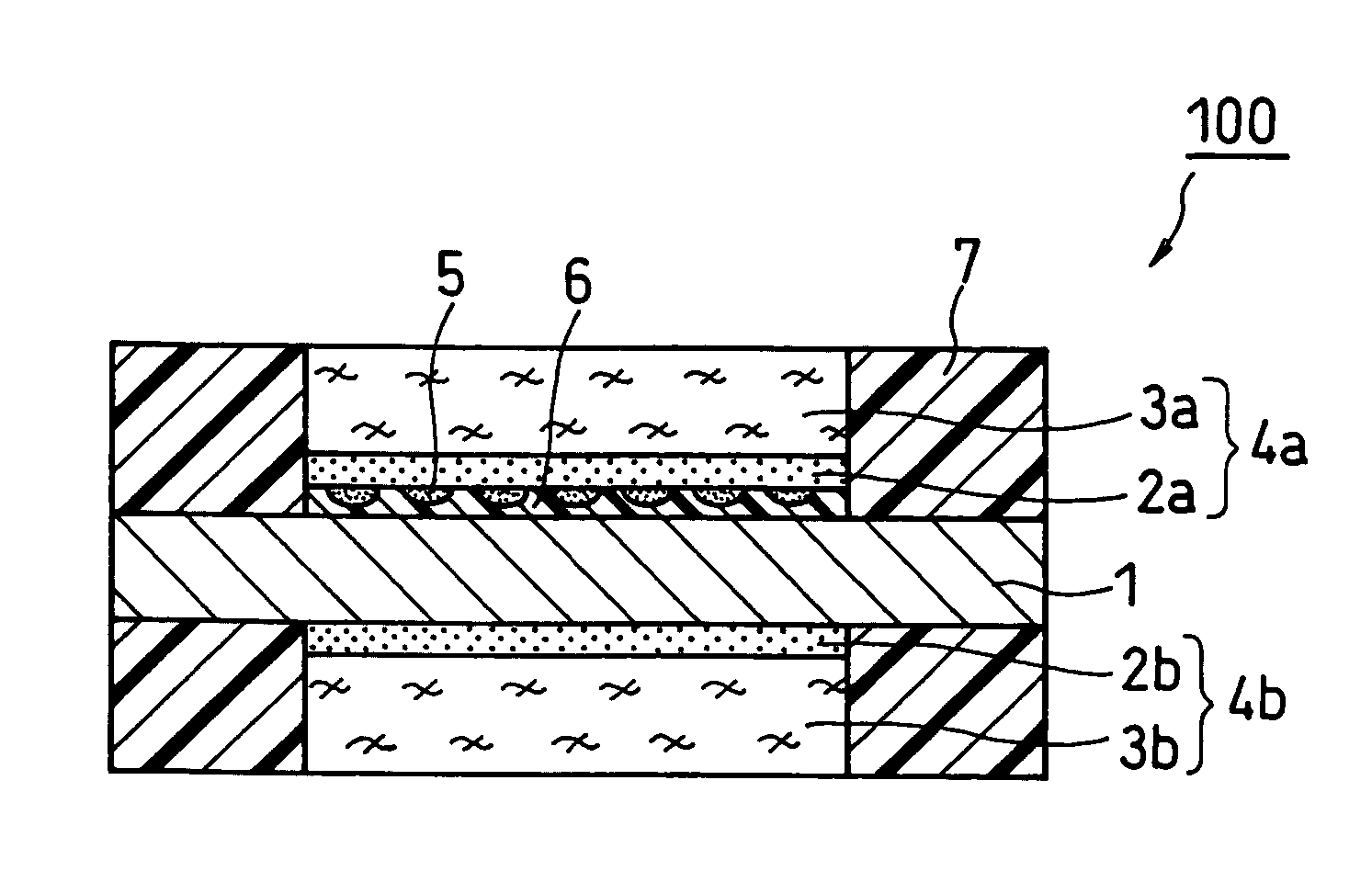
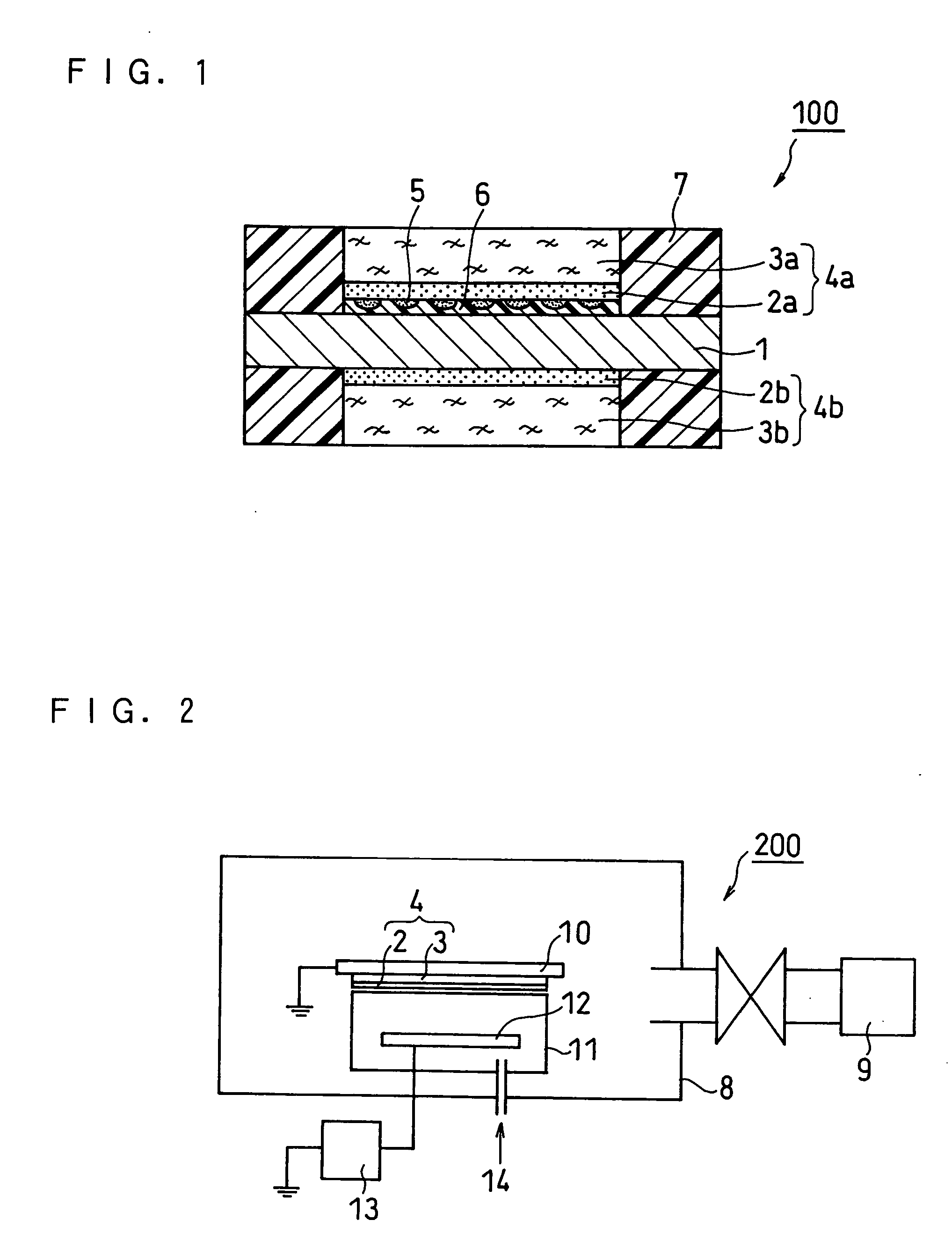
[0061]FIG. 1 is a schematic cross sectional view illustrating the structure of a membrane electrode assembly (MEA) of a fuel cell according to Embodiment 1 of the present invention. As shown in FIG. 1, a membrane electrode assembly 100 of a fuel cell of the present invention is composed of a hydrogen ion conductive polymer electrolyte membrane 1, an anode 4a and a cathode 4b positioned on each side of the polymer electrolyte membrane 1. The anode 4a is composed of an anode catalyst layer 2a and an anode diffusion layer 3a. The cathode 4b is composed of a cathode catalyst layer 2b and a cathode diffusion layer 3b.

[0062] On both sides of the polymer electrolyte membrane 1 are placed the anode catalyst layer 2a and the cathode catalyst layer 2b. On the outer side of the anode catalyst layer 2a is placed the anode diffusion layer 3a, and on the outer side of the cathode catalyst layer 2b is placed the cathode diffusion layer 3b.

[0063] Gas sealants 7 are placed on the outer periphery o...

embodiment 2

[0091]FIG. 5 is a schematic cross sectional view of a membrane electrode assembly (MEA) of a fuel cell according to Embodiment 2 of the present invention.

[0092] The MEA of Embodiment 2 of the present invention has the same structure as the MEA of Embodiment 1 of the present invention except that the electrolyte polymer layer 6 is not formed. Accordingly, the MEA of Embodiment 2 can be produced in the same manner as the MEA of Embodiment 1.

embodiment 3

[0093]FIG. 6 is a schematic cross sectional view illustrating the structure of a membrane electrode assembly (MEA) of a fuel cell according to Embodiment 3 of the present invention.

[0094] The MEA of Embodiment 3 of the present invention has the same structure as the MEA of Embodiment 1 of the present invention except that the discontinuous catalyst layer 5 is not formed. Accordingly, the MEA of Embodiment 3 can be produced in the same manner as the MEA of Embodiment 1.

[0095] The embodiments of the present invention have been described in detail above, but it should be understood that the present invention is not limited thereto.

[0096] The present invention is more specifically described below in the following examples, but it is to be understood that the present invention is not limited to the examples below.


PUM


Abstract

In order to prevent the crossover of an organic fuel such as methanol in a fuel cell and to exhibit excellent electricity generation characteristics without impairing the utilization efficiency of the fuel, at least either of (1) a discontinuous catalyst layer being formed on a surface of an anode catalyst layer and having a higher density (existence probability) of platinum type catalyst than the anode catalyst layer and (2) an electrolyte polymer layer is formed at the interface between the anode catalyst layer and a polymer electrolyte membrane.

Description

BACKGROUND OF THE INVENTION [0001] The present invention relates to a polymer electrolyte fuel cell that generates electricity using a fuel and an oxidant. [0002] As portable compact electronic devices such as cell phones, personal digital assistants (PDAs), notebook computers and camcorders become multifunctional and consume more electric power, they are required to have more electric power and longer continuous operating time. In order to meet this requirement, batteries having a higher energy density are in strong demand as power sources. Currently, lithium secondary batteries are mainly used as high energy density batteries. They are expected to have an energy density of about 500 Wh / L, 200 Wh / kg in around 2005, which is considered to be the limit of the energy density of lithium secondary batteries. Under the circumstances, early commercialization of polymer electrolyte fuel cells (PEFCs) is awaited as an alternative to lithium secondary batteries. [0003] Among PEFCs, active re...

Claims


Application Information

Patent Timeline
IPC IPC(8): B05D5/12H01M4/88H01M4/90H01M4/92H01M4/96H01M4/86H01M8/02H01M8/06H01M8/10
CPCH01M4/8642H01M4/8657H01M4/8828H01M4/8867H01M4/8882H01M4/8896Y02E60/50H01M8/04261H01M8/1004H01M8/1011H01M8/1013H01M2004/8684Y02E60/523H01M4/926H01M8/04197Y02P70/50
Inventor UEDA, HIDEYUKIAKIYAMA, TAKASHIYUASA, KOHJIOKADA, YUKIHIROSHIBUTANI, SATOSHI
Owner PANASONIC CORP
Why Eureka
Try Eureka