Light emitting device and illuminator using the same

a technology of light emitting device and illuminator, which is applied in the direction of discharge tube/lamp details, discharge tube luminescent screen, discharge tube/lamp details, etc., can solve the problems of energy loss and emission intensity reduction, and achieve the effect of maintaining charge compensation effect, reducing emission intensity, and reducing emission intensity

Inactive Publication Date: 2005-07-07
MITSUBISHI CHEM CORP
View PDF20 Cites 25 Cited by
  • Summary
  • Abstract
  • Description
  • Claims
  • Application Information

AI Technical Summary

Benefits of technology

[0148] For the purpose of accelerating crystallization of a complex oxide caused by the diffusion, in solid, of the divalent or trivalent metal element and emission center Eu2+ upon sintering, a monovalent, trivalent, tetravalent, pentavalent or hexavalent metal element as M2′ and M3′ and a monovalent, divalent, tetravalent, pentavalent or hexavalent metal element as M4′ may be introduced in a small amount within an extent not impairing the advantage of the present invention.
[0149] In one example, a portion of Ba2+ in a BaMgAl10O7:Eu phosphor can be substituted with an equimolar amount of Li+ and Ga3+ while maintaining charge compensation effects. In order to control emission wavelength or emission intensity, it may be substituted with a metal element such as Mn which will serve as a sensitizer.
[0150] The molar ratio f of Eu in the formula [2] is a number satisfying f≧0.11, preferably f≧0.15 and f≦0.99, preferably f≦0.65. When the molar ratio f of Eu2+ which is an emission center ion is too small, the emission intensity tends to become smaller. When f is too large, on the other hand, the emission intensity also tends to decrease owing to a phenomenon called concentration quenching.
[0151] The e stands for a number satisfying (e+f)≧0.9, preferably (e+f)≧0.95, more preferably (e+f)≧0.98 and (e+f)≦1.1, preferably (e+f)≦1.05, more preferably (e+f)≦1.02.
[0152] The g stands for a number satisfying g≧0.9 and g≦1.1.
[0153] The h stands for a number satisfying h≧9 and h≦11.

Problems solved by technology

Described specifically, in the case of a conventional phosphor excited by light (mercury emission line) having a wavelength of 254 nm, an increase in the concentration of an activator causes a phenomenon called concentration quenching, which leads to energy loss and lowering in emission intensity.

Method used


Image

  • Light emitting device and illuminator using the same
  • Light emitting device and illuminator using the same
  • Light emitting device and illuminator using the same

Examples


example 1

[0229] With pure water, 0.1055 mole of SrHPO4, 0.0352 mole of SrCO3, 0.0176 mole of SrCl2 and 0.0088 mole of Eu2O3 were pulverized and mixed in a wet-type ball mill made of alumina and containing beads. After drying, the resulting mixture was caused to pass through a nylon mesh. The pulverized mixture was sintered by heating at 1200° C. for 2 hours in an alumina crucible under a nitrogen gas stream containing 4% of hydrogen. The sintered mixture was then washed with water, dried and classified, whereby a phosphor Sr4.5Eu0.5(PO4)3Cl was prepared.

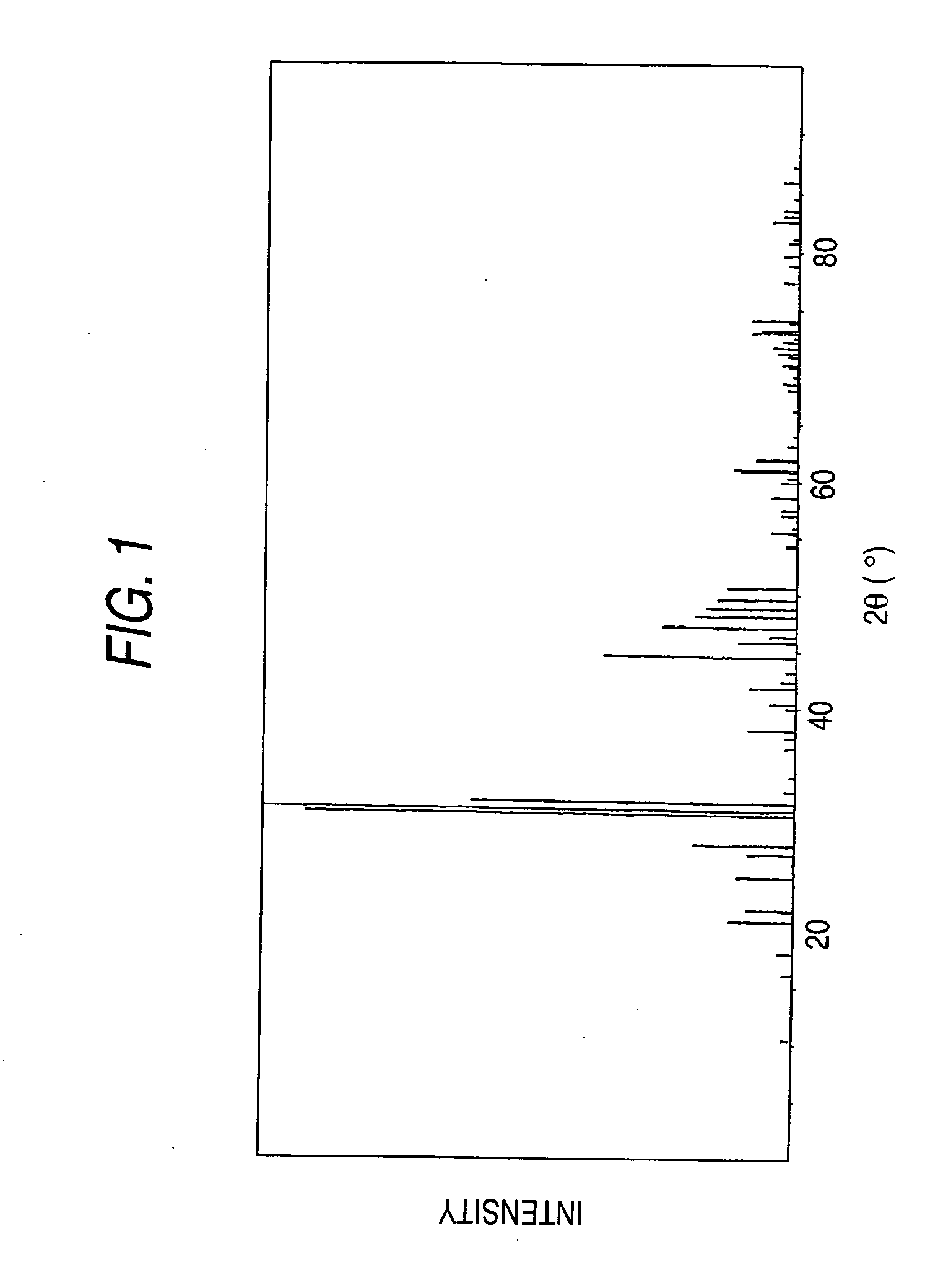
[0230] The X-ray diffraction pattern of the resulting phosphor is shown in FIG. 4. From the diagram, it has been found that the peak pattern of FIG. 4 is crystallographically identical to that of Sr5(PO4)3Cl of FIG. 1.

[0231] The emission spectrum of the resulting phosphor excited at 400 nm which is a dominant wavelength of the ultraviolet region of a GaN light emitting diode is shown in FIG. 5.

[0232] In Table 1, the wavelength of emission ...

example 2

[0234] In a similar manner to Example 1 except for the use of 0.1055 mole of SrHPO4, 0.0176 mole of SrCO3, 0.0176 mole of SrCl2 and 0.0176 mole of Eu2O3 as raw materials instead, a phosphor Sr4Eu1(PO4)3Cl was prepared.

[0235] The X-ray diffraction pattern of the resulting phosphor is shown in FIG. 6. From the diagram, it has been found that the peak pattern of FIG. 6 is crystallographically identical to that of Sr5(PO4)3Cl of FIG. 1.

[0236] The resulting phosphor was excited at 400 nm, that is, a dominant wavelength of the ultraviolet region of a GaN light emitting diode. The wavelength of its emission peak, relative emission intensity (i), a quantum absorption efficiency αq of the phosphor and a product αq·ηi of the quantum absorption efficiency αq and the internal quantum efficiency ηi of the phosphor as measured using a reflector having a reflectance of 98% are shown.

[0237] The Eu—Eu mean distance was 6.7 Å.

example 3

[0238] In a similar manner to Example 1 except for the use of 0.1055 mole of SrHPO4, 0.0176 mole of SrCl2 and 0.0264 mole of Eu2O3 as raw materials instead, a phosphor Sr3.5Eu1.5(PO4)3Cl was prepared.

[0239] The X-ray diffraction pattern of the resulting phosphor is shown in FIG. 7. From the diagram, it has been found that the peak pattern of FIG. 7 is crystallographically identical to that of Sr5(PO4)3Cl of FIG. 1.

[0240] The resulting phosphor was excited at 400 nm, that is, a dominant wavelength of the ultraviolet region of a GaN light emitting diode and emission spectrum was measured. The wavelength of its emission peak, relative emission intensity (i), and a quantum absorption efficiency αq of the phosphor and a product αq·ηi of the quantum absorption efficiency αq and the internal quantum efficiency ηi of the phosphor as measured using a reflector having a reflectance of 98% are shown.

[0241] The Eu—Eu mean distance was 5.9 Å.


PUM

PropertyMeasurementUnit
excitation wavelengthaaaaaaaaaa

Abstract

An object of the present invention is to provide a light emitting device having a high emission intensity, and a light emitting device having a high emission intensity and a good color rendering property. The present invention provides a light emitting device which comprises: a first light emitter emitting light of from 350 to 415 nm and a second light emitter emitting visible light by exposure to the light from the first light emitter, wherein said second light emitter comprises a phosphor capable of satisfying any one of the following conditions (i) to (iv): (i) the phosphor comprises: (a) a crystal phase whose Eu concentration providing the maximum emission intensity at any one of excitation wavelengths of from 350 to 415 nm is higher than that providing the maximum emission intensity at an excitation wavelength of 254 nm; and (b) a crystal phase which is activated by Eu having at least 1.1 times the concentration providing the maximum emission intensity at an excitation wavelength of 254 nm and 0.5 to 9 times the concentration providing the maximum emission intensity at an excitation frequency of 400 nm: (ii) the phosphor comprises a crystal phase having an Eu—Eu mean distance, as calculated from the Eu concentration in a crystal matrix, of 4 Å or greater but not greater than 11 Å: [0001](iii) the phosphor has a quantum absorption efficiency αq of 0.8 or greater: [0002](iv) the phosphor has a product αq·ηi of a quantum absorption efficiency αq and an internal quantum efficiency ηi of 0.55 or greater.

Description

FIELD OF THE INVENTION [0003] The present invention relates to a light emitting device, more specifically, to a light emitting device having a high color rendering property under any using environment and capable of emitting light with high intensity, which device is obtained by using, in combination, a first light emitter which emits light in the ultraviolet to visible light region, driven by a power source, and as a wavelength conversion material, a second light emitter which emits longwave visible light, absorbing the light in the ultraviolet to visible light region and has a phosphor whose matrix compound contains an emission center ion. BACKGROUND ART [0004] With a view to generating various colors including white uniformly with a good color rendering property by mixing blue, red and green colors, a light emitting device which radiates colored light from a first light emitter such as LED or LD to a phosphor as a second light emitter to cause color conversion is proposed. For ex...

Claims


Application Information

Patent Timeline
Patent Type & Authority Applications(United States)
IPC IPC(8): C09K11/77H01L27/15H01L33/50H05B33/14
CPCC09K11/7734C09K11/7737H01L33/502C09K11/7739C09K11/7738H01L2924/181H01L2224/48091H01L2224/48247C09K11/77342H01L2924/00014H01L2924/00012
Inventor SETO, TAKATOSHIKIJIMA, NAOTOOHNO, AKIRA
Owner MITSUBISHI CHEM CORP
Why Eureka
Try Eureka