Multi-spectral laser array and optical system

a laser array and optical system technology, applied in the field of electronic display and printing systems, can solve the problems of system sensitive to the potential failure of the laser source, limited development of laser projection systems, and typically intended to be multi-color,

Inactive Publication Date: 2005-07-07
EASTMAN KODAK CO
View PDF9 Cites 74 Cited by
  • Summary
  • Abstract
  • Description
  • Claims
  • Application Information

AI Technical Summary

Problems solved by technology

The development of laser projection systems, which are typically intended to be multi-color, have been generally limited by the minimal availability of useful visible wavelength lasers.
Notably, however, most of the laser printing systems described in the prior art are monochrome, and utilize infrared lasers, rather than the multiple visible spectrum lasers desired for laser projection.
However, the high power single beam lasers are typically too large and expensive to use in many printing applications.
Moreover, such systems are sensitive to the potential failure of the laser source.
On the other hand, this type of system is susceptible to emitter failure, and the consequent introduction of a pattern error.
It can also be difficult to properly modulate the diodes, due both to the high current inputs needed by the diodes and the sensitivity to thermal and electrical crosstalk effects between laser emitters.
Certainly numerous other modulator array technologies have been developed, including most prominently the digital mirror device (DMD) and liquid crystal displays (LCDs), but these devices are less optimal as linear array modulators which experience the high incident power levels needed in many printing and display applications.
Even with laser array consisting of long 1-D multimode emitters, laser filamentation, residual coherence, and non-uniform gain profiles can cause significant macro- and micro-non-uniformities in the array direction light emission profiles, which can result in the modulator illumination being significantly non-uniform.
As with the comparable laser printing systems, U.S. Pat. No. 5,982,553 s

Method used


Image

  • Multi-spectral laser array and optical system
  • Multi-spectral laser array and optical system
  • Multi-spectral laser array and optical system

Examples


Embodiment Construction

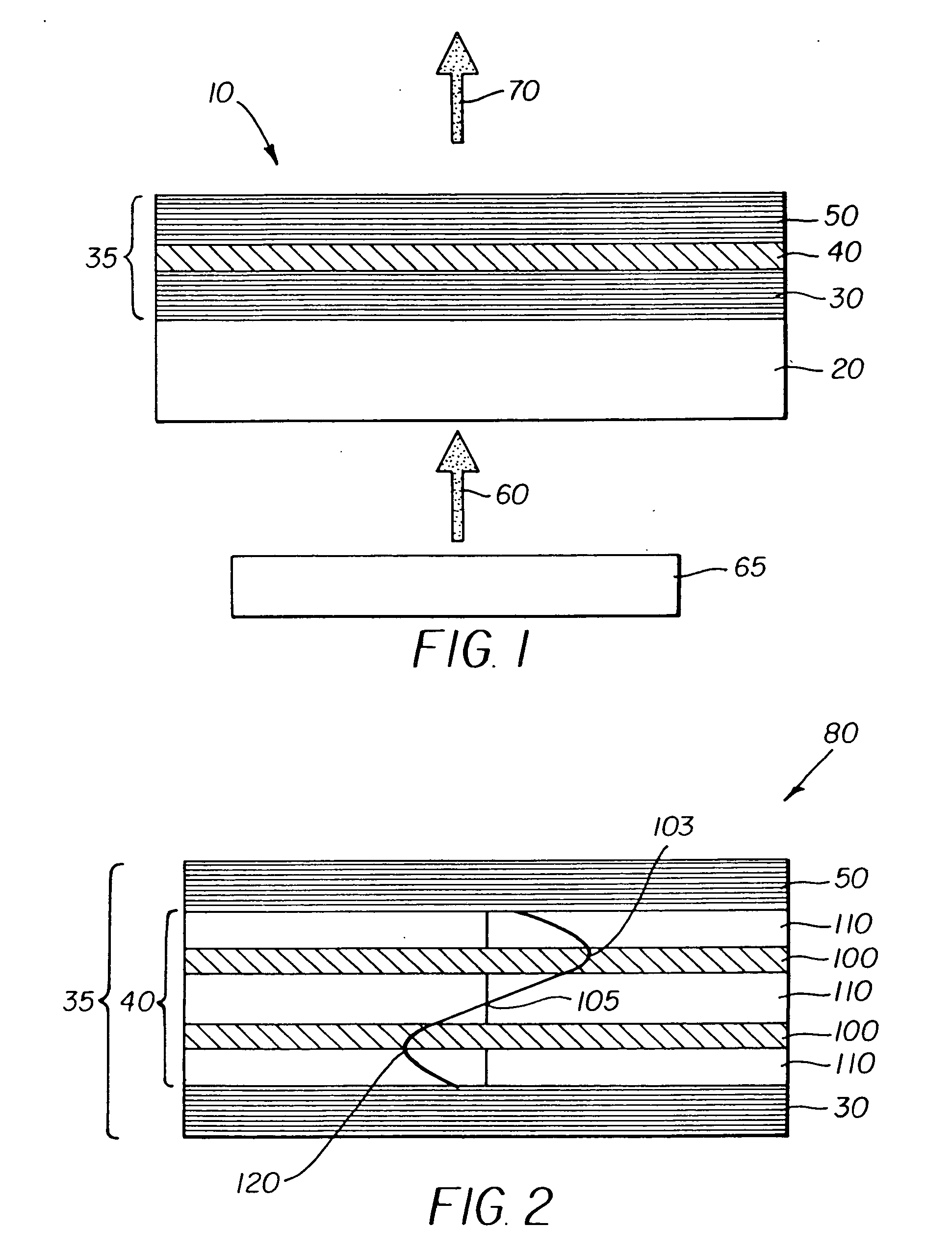
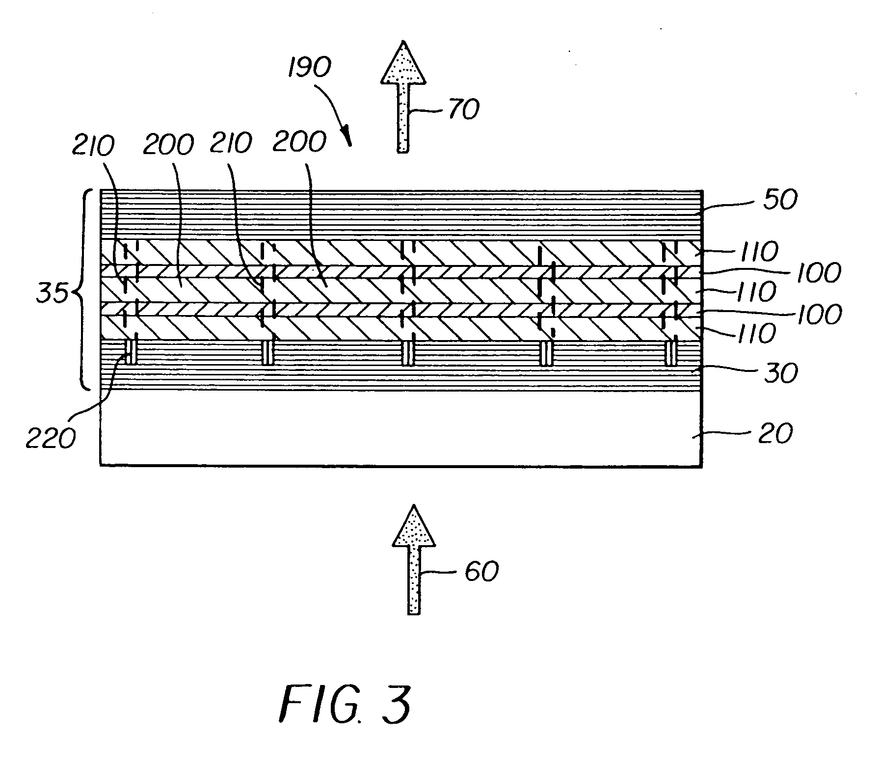
[0045] A schematic of a vertical cavity organic laser structure 10 is shown in FIG. 1. The substrate 20 can either be light transmissive or opaque, depending on the intended direction of optical pumping and laser emission. Light transmissive substrates 20 may be transparent glass, plastic, or other transparent materials such as sapphire. Alternatively, opaque substrates including, but not limited to, semiconductor material (e.g. silicon) or ceramic material may be used in the case where both optical pumping and emission occur through the same surface. On the substrate is deposited a bottom dielectric stack 30 followed by an organic active region 40. A top dielectric stack 50 is then deposited. The organic laser film structure 35 comprises the combination of the bottom dielectric stack 30, the organic active region 40, and the top dielectric stack 50. A pump light source 65 provides a pump beam 60 that optically pumps the vertical cavity organic laser structure 10. The source of the ...


PUM


Abstract

An organic vertical cavity laser light producing device (10) comprises a substrate (20). A plurality of laser emitters (200) emits laser light in a direction orthogonal to the substrate. Each laser emitter within the plurality of laser emitters has a first lateral mode structure in a first axis orthogonal to the laser light direction and has a second lateral mode structure in a second axis orthogonal to both the laser light direction and the first axis. Each laser emitter comprises a first mirror provided on a top surface of the substrate (20) and is reflective to light over a predetermined range of wavelengths. An organic active region (40) produces laser light (350). A second mirror is provided above the organic active region and is reflective to light over a predetermined range of wavelengths. A pumping means excites the plurality of laser emitters.

Description

CROSS REFERENCE TO RELATED APPLICATIONS [0001] This is a continuation-in-part of application Ser. No. 10 / 304,078, filed Nov. 25, 2002, entitled ORGANIC VERTICAL CAVITY LASER AND IMAGING SYSTEM, by Kurtz et al.FIELD OF THE INVENTION [0002] The present invention relates to electronic display and printing systems generally, and more particularly to electronic display and printing systems that employ organic laser light sources. BACKGROUND OF THE INVENTION [0003] Laser based electronic imaging systems have been developed for use both in projection display, and even more extensively, for printing applications. In particular, laser projection display systems have been developed with several basic architectures, which include vector scanning, raster scanning, one-dimensional (1-D) scanning, and two-dimensional (2-D) area imaging systems. The development of laser projection systems, which are typically intended to be multi-color, have been generally limited by the minimal availability of us...

Claims


Application Information

Patent Timeline
IPC IPC(8): G02B27/10H01S3/08H01S3/10H01S3/14H01S5/00H01S5/04H01S5/183H01S5/30H01S5/36H01S5/40H01S5/42H04N9/31
CPCH01S5/005H01S5/041H01S5/18319H01S5/18383H04N9/3197H01S5/4075H01S5/4093H01S5/423H04N9/3161H01S5/36
Inventor KURTZ, ANDREW F.KRUSCHWITZ, BRIAN E.KAHEN, KEITH B.
Owner EASTMAN KODAK CO
Why Eureka
Try Eureka