Mischmetal oxide TBC

a technology of mischmetal oxide and tbc, which is applied in the field of thermal barrier coatings comprising mischmetal oxide, can solve the problems of high temperature durability of engine components that must correspondingly increase, the cost and time-consuming application of tbc by eb-pvd process, and the inability to meet the requirements of high-temperature durability of engine components, etc., to achieve thin tbc layer, reduce the conductivity of tb

Inactive Publication Date: 2005-09-08
GENERAL ELECTRIC CO
View PDF16 Cites 19 Cited by
  • Summary
  • Abstract
  • Description
  • Claims
  • Application Information

AI Technical Summary

Benefits of technology

[0017] An advantage of the present invention is that the use of the rare earth oxides in the mischmetal, which have lower thermal conductivity than yttria-stabilized zirconia, reduces the conductivity of the TBC, allowing a thinner TBC layer to be applied to the turbine engine component.
[0018] Another advantage of the present invention is erosion resistance of the TBC layer is improved through the use of the rare earth oxides in the mischmetal, which are believed to have at least comparable erosion resistance compared to yttria-stabilized zirconia.
[0019] Another advantage of the present invention is that the impact resistance of the TBC layer is improved through the use of the rar

Problems solved by technology

However, as operating temperatures increase, the high temperature durability of the components of the engine must correspondingly increase.
While significant advances have been achieved with iron, nickel and cobalt-base superalloys, the high-temperature capabilities of these alloys alone are often inadequate for components located in certai

Method used


Image

  • Mischmetal oxide TBC
  • Mischmetal oxide TBC
  • Mischmetal oxide TBC

Examples


Embodiment Construction

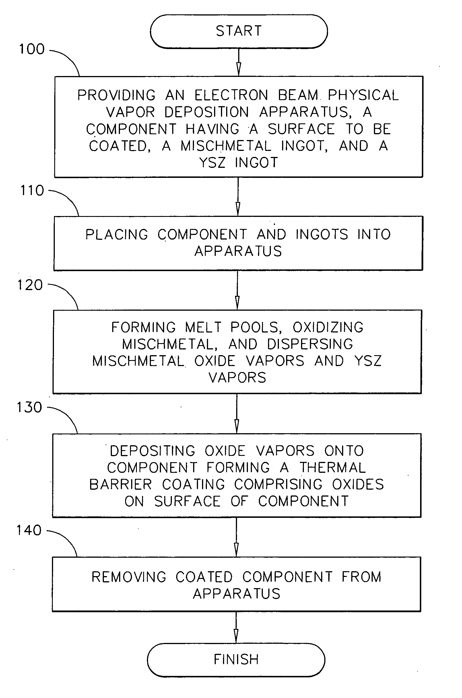
[0030] Referring now to FIG. 1 there is shown the method of the present invention for applying of applying a mischmetal oxide TBC to a superalloy turbine engine component of the present invention. The initial step 100 of the process comprises providing an EB-PVD apparatus, a superalloy turbine engine component comprising a surface to be coated, a first mischmetal ingot, and a second oxide ingot comprising another oxide material selected from the group consisting of yttria-stablized zirconia, zirconia, yttria, hafnia, at least one other rare earth oxide, and combinations thereof. The mischmetal ingot preferably comprises, based on 100% of weight, about 30% to about 70% Ce by weight, about 19% to about 56% La by weight, about 2% to about 7% Pr by weight and from about 0% to about 20% Nd by weight. The preferred mischmetal ingot may also contain impurities, such as iron and / or silicon. In a more preferred embodiment, the mischmetal ingot comprises, based on 100% of weight, about 30% to...


PUM

PropertyMeasurementUnit
Lengthaaaaaaaaaa
Lengthaaaaaaaaaa
Lengthaaaaaaaaaa

Abstract

The present invention is a turbine engine component comprising a superalloy substrate, a bond coat overlying the substrate having a thickness in the range of about 0.0005 inch to about 0.005 inch, a thin alumina scale overlying the bond coat, and a thermal barrier coating (TBC) overlying the thin alumina scale, the TBC having a thickness in the range of about 0.0025 inch to about 0.010 inch, and comprising at least mischmetal oxide. The present invention is also a method for the application of a thermal barrier coating to a superalloy turbine engine component comprising the steps of: providing an electron beam physical vapor deposition apparatus, providing a turbine engine component comprising a surface to be coated, providing an oxide ingot comprising mischmetal oxide and another oxide material selected from the group consisting of yttria-stablized zirconia, zirconia, yttria, hafnia, at least one other rare earth oxide, and combinations thereof, placing the component and the ingot into the apparatus, drawing a vacuum within the apparatus, forming a melt pool on the ingot, dispersing mischmetal oxide vapors and yttria-stabilized zirconia vapors, depositing the mischmetal oxide vapors and the yttria-stabilized zirconia vapors onto the surface to be coated, said deposition forming a thermal barrier coating having a thickness in the range of about 0.0025 inch to about 0.010 inch.

Description

FIELD OF THE INVENTION [0001] The present invention relates to thermal barrier coatings for components exposed to high temperatures, such as the hostile thermal environment of a gas turbine engine. More particularly, this invention is directed to thermal barrier coatings comprising the mischmetal oxide. BACKGROUND OF THE INVENTION [0002] Higher operating temperatures for gas turbine engines are continuously sought in order to increase their efficiency. However, as operating temperatures increase, the high temperature durability of the components of the engine must correspondingly increase. While significant advances have been achieved with iron, nickel and cobalt-base superalloys, the high-temperature capabilities of these alloys alone are often inadequate for components located in certain sections of a gas turbine engine, such as the turbine, combustor and augmentor. A common solution is to thermally insulate such components in order to minimize their service temperatures. For this...

Claims


Application Information

Patent Timeline
IPC IPC(8): B32B9/00
CPCC23C14/08C23C14/24C23C28/321C23C28/325C23C28/3455F01D5/288Y10T428/12771F05D2230/90F05D2300/15F05D2300/611F05D2300/134Y10T428/12806Y10T428/12549F05D2230/313
Inventor JOHNSON, LYMAN A.BRUCE, ROBERT WILLIAMJOHNSON, MARY B.
Owner GENERAL ELECTRIC CO
Why Eureka
Try Eureka