
Integrated photoelectrochemical cell and system having a solid polymer electrolyte

a photoelectrochemical cell and solid polymer technology, applied in the direction of electrochemical generators, sustainable manufacturing/processing, final product manufacturing, etc., can solve the problems of large amount, inconvenient operation, and insufficient voltage generation of photovoltaic cells and electrodes, etc., to achieve high conversion efficiency and low cost

Inactive Publication Date: 2005-09-22
UNIVERSITY OF TOLEDO
View PDF19 Cites 50 Cited by
  • Summary
  • Abstract
  • Description
  • Claims
  • Application Information

AI Technical Summary

Benefits of technology

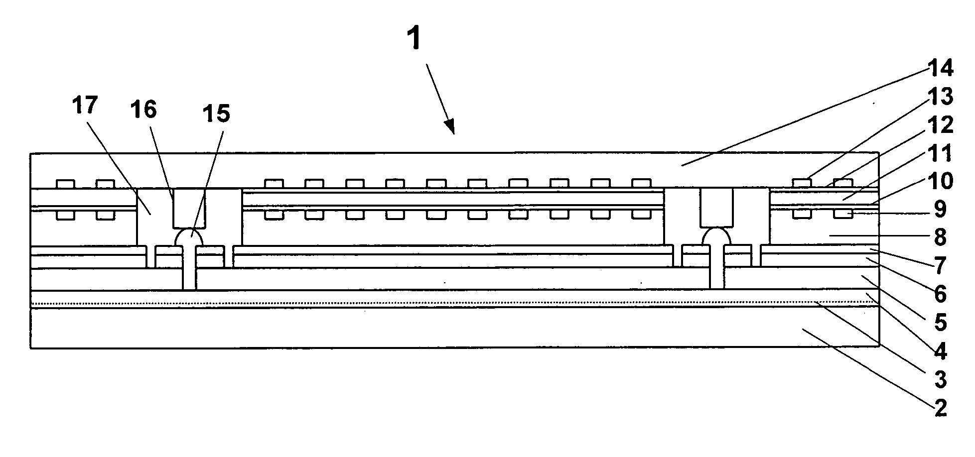
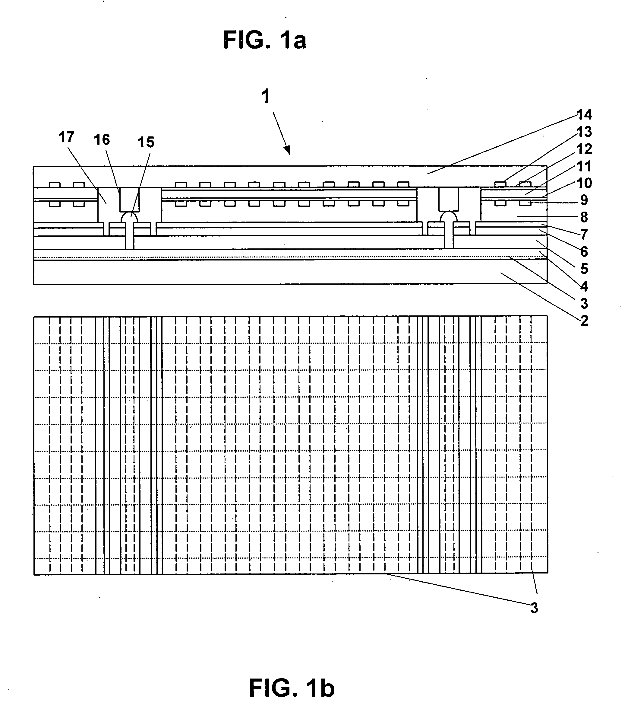
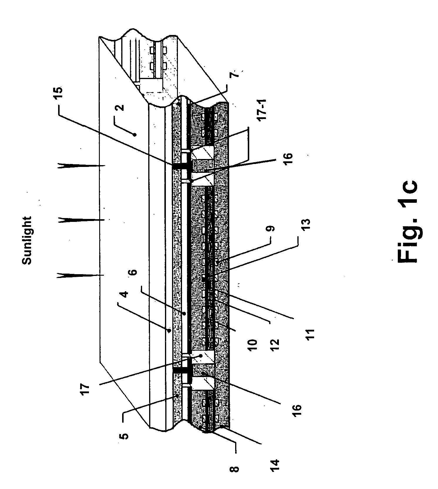
[0019] This instant invention provides a PEC cell that splits water under radiation and generates hydrogen and oxygen. This PEC cell integrates multiple-junction stacked photovoltaic structure (PV structure), to generate electricity, and a solid polymer electrolyte membrane electrode assembly (MEA) to electrolyze water, through novel interconnect schemes that lead to a device that has a high conversion efficiency, that is stable and can be made at low cost. One side of the photovoltaic structure is in direct contact with one electrode of the MEA while the other side (radiation entering side) connects to the opposite side of the MEA through appropriate interconnects such as via slots or via holes.
[0024] Water, needed for the electrolysis reaction, can be injected into the MEA using multiple methods. For example, water can be directed into the MEA through one or both of the gas outlet channels. The advantage of directing water through these channels is that water flushes out the gas bubbles and rapidly moves gas bubbles away from the electrodes for enhanced electrolysis.
[0025] An interconnect between the PV structure the MEA is accomplished in such a way that 1) the voltage from the PV structure is applied to the MEA; 2) radiation to the PV structure is not blocked; 3) hydrogen and oxygen can be directed out of the MEA effectively and water can be directed into the system effectively; 4) the electrical loss, if any, between PV structure and MEA is low; and, 5) the device can be fabricated using low-cost methods. In one embodiment, the PV structure is fabricated on a glass substrate. In certain embodiments, laser scribing is used to remove the photovoltaic semiconductor layers. MEAs are bonded to the PV structure with electrically conducting material. The conducting electrode is applied at the scribed locations to achieve interconnection between the radiation side of the PV structure and the opposite side of the MEA electrode.
[0028] These above-disclosed PEC cell and system offer significant advantages such as high conversion efficiency, efficient electrolysis, low cost, and high durability. Hydrogen fuels generated using such a PEC system contain extremely low amount of carbon monoxide, making such hydrogen ideal for PEM fuel cell (PEMFC) where Pt is used as a catalyst. It is understood that Pt can be poisoned by CO gas and this would result in reduced performance. The above-mentioned PEC system, when used in combination with portable fuel cells, provides distributed, and portable, power generation. The energy can be stored in hydrogen form. Since there is radiation such as sunlight everyday, the required storage for such combined PEC / PEMFC system does not need to be large, thus resulting in reduced cost. The PEC system can be made lightweight and flexible, depending on the substrate selection and system material selection.

Problems solved by technology

However, the reforming process, the main process that is used in today's hydrogen production, still uses petroleum-based products as the raw material and still emits large amounts of CO2.
However, indirect photo-electrolysis, in which the photovoltaic cells and electrodes are separated and connected electrically using external wires, is not cost-effective.
However, the prior art devices and methods described and disclosed in these above mentioned patents and publications have at least one of the following shortcomings: the photovoltaic cell does not generate sufficient voltage to split water, the photovoltaic cell needs an external electrical bias for the electrolysis, the photovoltaic device will not survive for extended use in the electrolyte due to inappropriate protection, the photovoltaic device cannot be fabricated using low-cost methods, and / or the photovoltaic device does not have potential for high conversion efficiency.

Method used


Image

  • Integrated photoelectrochemical cell and system having a solid polymer electrolyte
  • Integrated photoelectrochemical cell and system having a solid polymer electrolyte
  • Integrated photoelectrochemical cell and system having a solid polymer electrolyte

Examples


example 1

[0083] An example of the semiconductor junction / stack 5 in the PV structure 4-7 is a two-junction a-Si / a-SiGe solar cell. The total voltage can be made to be around to 1.6V or higher at operating point, when relative low Ge content is used for the absorber layers. In one specific embodiment, the structure comprises: glass / grids / SnO / a-SiC p / a-Si intrinsic / a-Si n / s-SiC p / a-SiGe intrinsic / a-Si n / ZnO / aluminum.

[0084] The thickness of the respective layers are approximately: 1 mm / 10 μm / 1 μm / 10 nm / 150 nm / 10 nm / 10 nm / 150 nm / 200 nm / 150 nm, respectively, for optimum sunlight radiation.

[0085] In certain specific embodiments, the length of each sections of end plate 8 is around 5 to 10 cm while the width of the laser scribing is about 0.1 mm.

[0086] In certain specific embodiments, the thickness and bandgap of a-Si and a-SiGe intrinsic layers may be adjusted such that the two component solar cells generate about the same electrical current under the radiation specified. For electron radiation...

example 2

[0090] There are different ways water can be directed into the MEA. In addition to the methods described above, another way to direct water into the electrolyte is to create channels in the solid polymer electrolyte. In such embodiment, water can flow directly into the electrolyte instead of going through the channels on the end plate. Also, in other embodiments, water can flow only through the end plate that is closest to the electrode where water is consumed.


PUM

PropertyMeasurementUnit
voltageaaaaaaaaaa
voltageaaaaaaaaaa
total voltageaaaaaaaaaa

Abstract

A photoelectrochemical (PEC) cell includes a photovoltaic electrode that generates voltage under radiation; a solid membrane electrode assembly that includes at least one solid polymer electrolyte and first and second electrodes; a mechanism that collect gases from oxidation and reduction reactions; and an electrical connection between the photovoltaic electrode and the solid membrane electrode assembly. A PEC system and a method of making such PEC cell and PEC system are also disclosed.

Description

CROSS REFERENCE TO RELATED APPLICATION [0001] This application is a continuation of co-pending International Patent Application No. PCT / US2003 / 37733 filed Nov. 24, 2003, claiming priority to U.S. Patent Application No. 60 / 428,841 filed Nov. 25, 2002. International Patent Application PCT / US0 / 37733 was published as WO 04 / 049459 on Jun. 10, 2004 in English under PCT Article 21(2).[0002] This invention was made with Government support under National Renewable Energy Laboratory (NREL) contract No. NDJ-1-30630-08 awarded by the Department of Energy, and under ARL-WPAFB Grant “Photovoltaic Hydrogen for Portable, On-Demand Power” awarded to the University of Toledo under subcontract 03-S530-0011-01C1 under the primary contract F33615-02-D-2299 through the Universal Technology. The government has certain rights in this invention.FIELD OF THE INVENTION [0003] The instant invention relates generally to the generation of hydrogen and oxygen from water through a photo-electrolysis process and mo...

Claims


Application Information

Patent Timeline
Patent Type & Authority Applications(United States)
IPC IPC(8): C25B1/00H01G9/20H01L31/00H01L31/04H01L31/18H01M4/04H01M6/30H01M14/00
CPCC25B1/003H01G9/2009Y02E10/542H01M14/005H01G9/2045Y02E60/36Y02P20/133Y02P70/50C25B1/55
Inventor DENG, XUNMINGXU, LIWEI
Owner UNIVERSITY OF TOLEDO
Learn More