Apparatus for the evaporation of aqueous organic liquids and the production of powder pre-forms in flame hydrolysis processes

a technology of flame hydrolysis and evaporator, which is applied in the direction of evaporation, lighting and heating apparatus, and separation processes. it can solve the problems of significant pressure fluctuations, unsteady flow rate of vapor to the end of the tube, and discontinuous dispensing of precursor vapors

Inactive Publication Date: 2005-09-22
GENERAL ELECTRIC CO
View PDF23 Cites 73 Cited by
  • Summary
  • Abstract
  • Description
  • Claims
  • Application Information

AI Technical Summary

Problems solved by technology

One problem associated with such conventional evaporator assemblies is a large pressure drop across the evaporator leading to discontinuous dispensing of precursor vapors.
In tube-type vaporizers, the fluid boils inside a narrow tube and produces slugs of gases that cause significant fluctuations in pressure and an unsteady flow rate of vapor to the end of the tube.
Such dispensing is disruptive to the steady flame operation in a flame hydrolysis process.
Due to an unsteady state operation, the addition of fluid as a batch or at a constant rate into the vessel does not immediately result in the production of a steady state vapor flow rate delivered by the evaporator.
The result is poor control of precursor vapor delivery flow at the flame hydrolysis process.
Typically, the fluid dribbles across the plate as a narrow stream and in a random fashion such that a significant fraction of the heating surface is not covered by a liquid film resulting in very ineffective vaporization.
In summary, conventional methods of evaporating fluids and producing powder pre-forms use evaporator assemblies that do not enable steady and controlled dispensing of vapor at the flame hydrolysis system.

Method used


Image

  • Apparatus for the evaporation of aqueous organic liquids and the production of powder pre-forms in flame hydrolysis processes
  • Apparatus for the evaporation of aqueous organic liquids and the production of powder pre-forms in flame hydrolysis processes
  • Apparatus for the evaporation of aqueous organic liquids and the production of powder pre-forms in flame hydrolysis processes

Examples


third embodiment

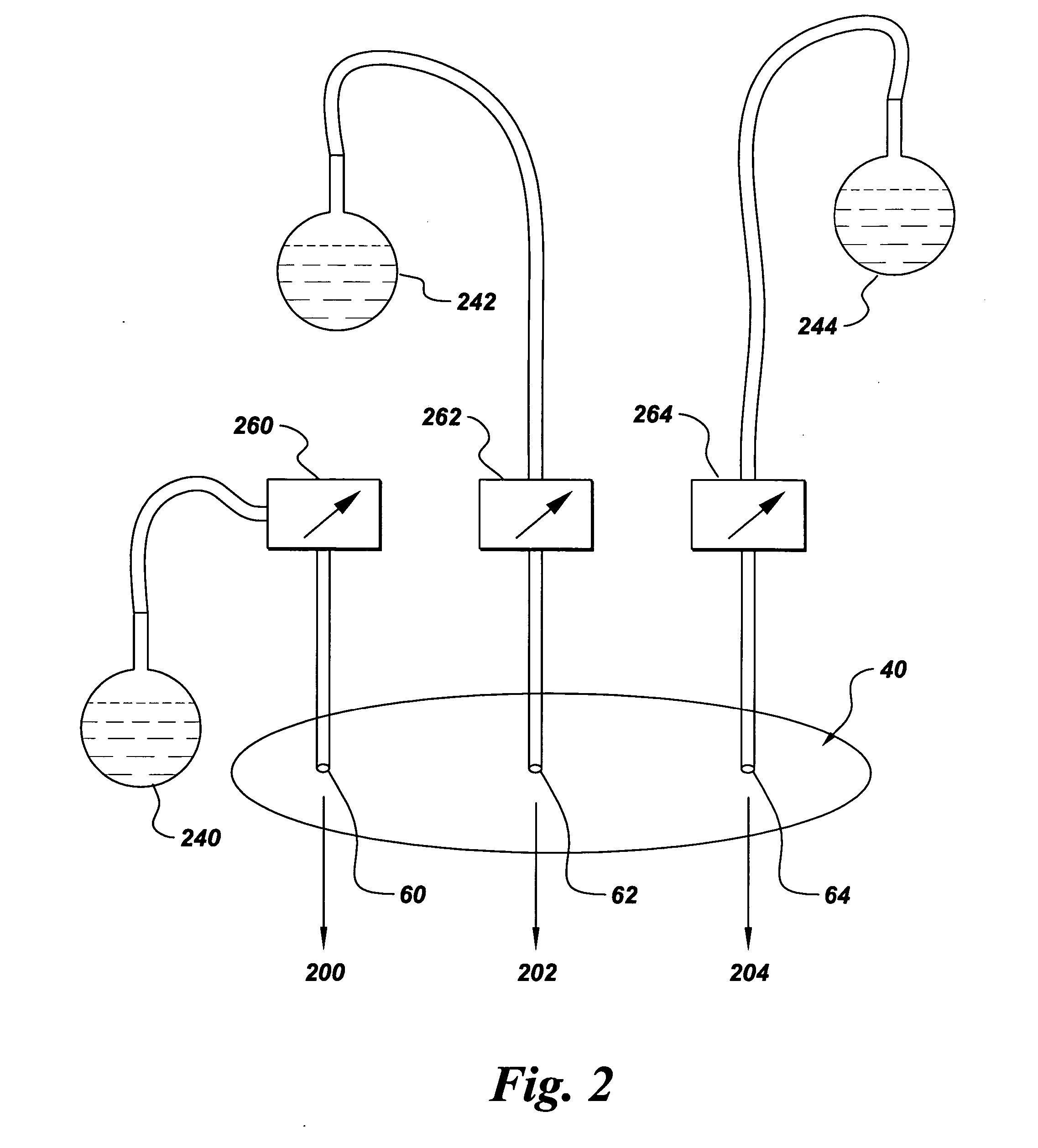
[0018] In the present invention, shown in FIG. 3, the housing 40 has a plurality of outlets 80, 82, 84. The plurality of outlets 80, 82, 84 connect to burner supply lines 300, 302, 304 via downstream pressure regulators 280, 282, 284. In some embodiments, the downstream pressure regulators 280, 282, 284 are set to the same pressure with respect to one another and in other embodiments, they are set to different pressures with respect to one another to provide a blend of organic vapor in different, proportions as per need. Since the concentration (or molar concentration) of individual vapor components depends upon the partial pressure of the component, a manipulation of downstream pressure regulators 280, 282, 284 permits a manipulation of the concentration of organic vapors 220, 222, 224. Thus, the organic vapors may be mixed and blended in any desired proportion.

[0019] Organic liquid evaporation systems that do not feature a constant internal fluid pressure within housing 40 are oft...

fourth embodiment

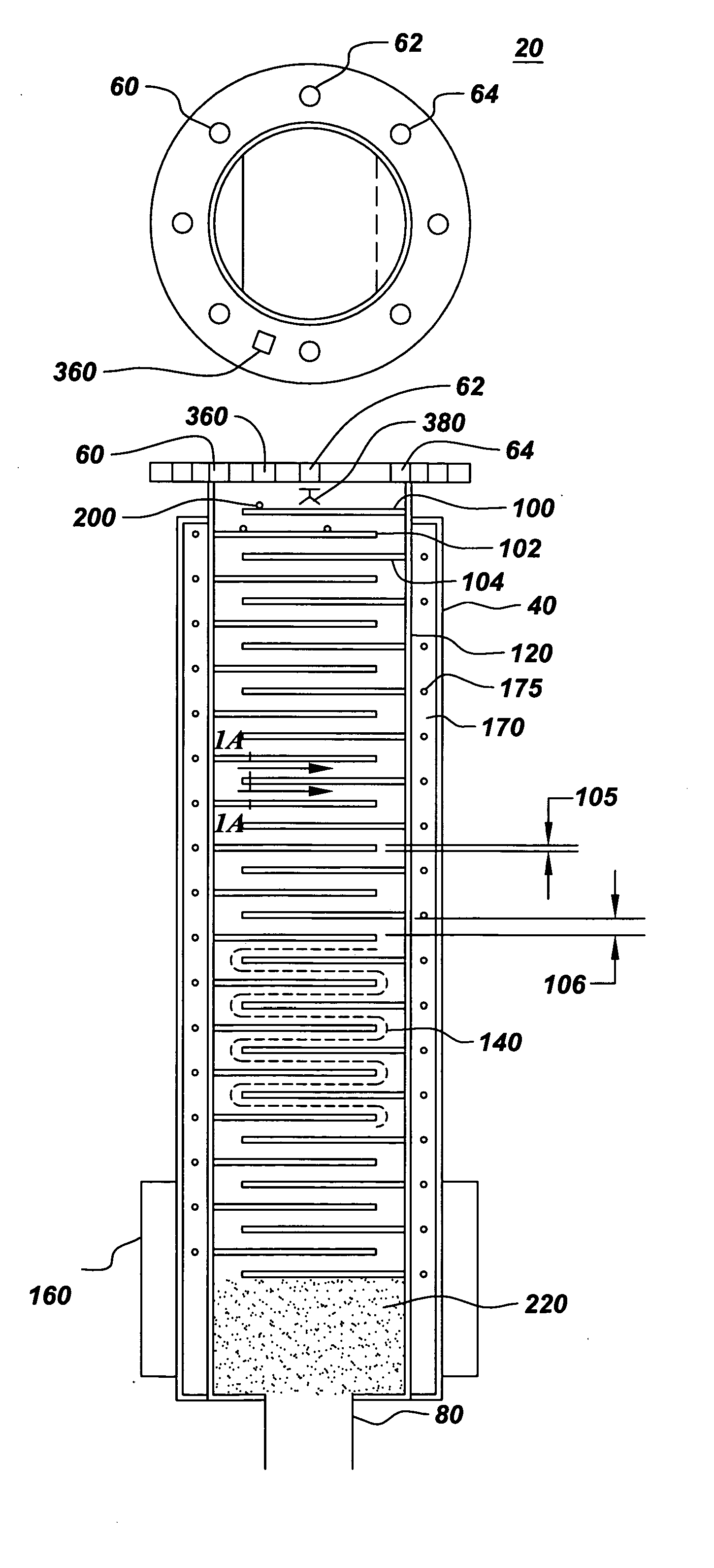
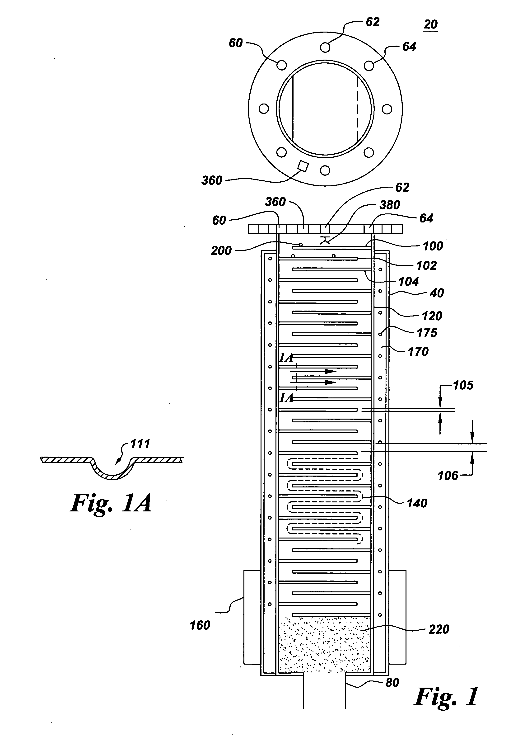
[0020] In the present invention, the housing 40 further comprises a carrier gas inlet 360 (FIG. 1) for delivery of a carrier gas 370 into the housing 40. The use of carrier gas 360 is preferred and is not mandatory for the functioning of the organic liquid evaporation system 20 claimed in this invention. The uniform dispensing of vapor 220 is aided by the use of carrier gas 370 as an addition over the constant internal pressure inside housing 40 that delivers uniform and regulated dispensing of vapor 220. Vapor 220 comprises an organic vapor phase of an element selected from the group consisting of aluminum, silicon, germanium, titanium, zirconium, boron, magnesium, calcium and combinations, mixtures, composites, alloys, and functionally graded combinations-thereof.

[0021] In some embodiments of the present invention, the organic liquid evaporation system 20 further comprises a droplet-generating device 380 (FIG. 4) for example, a fogger, spray nozzle, ultrasonic device and combinati...


PUM

PropertyMeasurementUnit
thicknessaaaaaaaaaa
thicknessaaaaaaaaaa
pressureaaaaaaaaaa

Abstract

An organic liquid evaporation system is disclosed. The organic liquid evaporation system comprises a housing having at least one inlet and at least one outlet. At least a first evaporator plate radially extending from a sidewall of the housing, and at least a second evaporator plate radially extending from a sidewall of the housing define a serpentine flow path within the housing. A heating source is in thermal communication with the first evaporator plate and the second evaporator plate, wherein the heating source provides heat to the first and second evaporator plates to evaporate organic liquid introduced within the inlet to produce a vapor through the outlet. A method for preparing powder pre-forms and oxide soot using the organic liquid evaporation system is also disclosed.

Description

BACKGROUND OF INVENTION [0001] This invention relates to an evaporation device. More particularly, this invention relates to an evaporator to produce powder performs from aqueous, organic fluids. [0002] Evaporators are widely used in catalysis, materials processing and in healthcare to produce finely dispersed particulates having a high surface area. One feature of these devices is a heating plate that heats a liquid precursor to a vapor. Vaporized particulates are collected on a substrate and compacted, and optionally heat-treated or sintered to yield a structured material possessing the desired properties. [0003] Liquid precursor evaporation has been conventionally performed using a variety of devices, including but not limited to, tube-type vaporizers, pot-type vaporizers, single-plate slanted vaporizers, vertical falling film evaporators, droplet-generating hollow shafts that spray fluid droplets, packed column evaporators where fluid is vertically sprayed onto a porous packed c...

Claims


Application Information

Patent Timeline
Patent Type & Authority Applications(United States)
IPC IPC(8): B01B1/00B01D1/00B01D1/14B01D1/24
CPCB01B1/005B01D1/24B01D1/0088B01D1/007
Inventor GIDDINGS, ROBERT ARTHURAYALA, RAUL EDUARDO
Owner GENERAL ELECTRIC CO
Why Eureka
Try Eureka