
Method and apparatus of removing nitrogen

a technology of nitrogen removal and nitrogen concentration, applied in the direction of chemistry apparatus and processes, biological water/sewage treatment, water/sludge/sewage treatment, etc., can solve the problem of difficult to accurately control the ratio closer to this value, and the method has a difficult problem, so as to improve the performance of anaerobic ammonium oxidation, reduce the concentration of nitrite nitrogen, and improve the effect of nitrogen removal

Inactive Publication Date: 2005-09-29
HITACHI LTD
View PDF4 Cites 20 Cited by
  • Summary
  • Abstract
  • Description
  • Claims
  • Application Information

AI Technical Summary

Benefits of technology

[0017] The present invention was attained in view of these circumstances. The present invention can not only overcome the first to third problems but also improve the performance of anaerobic ammonium oxidation, and further directed to providing a method and apparatus of removing nitrogen without increasing the size of the apparatus.
[0036] As described in the above, according to the method and apparatus of removing nitrogen of the present invention, it is possible to solve the problems related to control of ammonium (NH4) nitrogen-to-nitrite (NO2) nitrogen ratio, inhibition of the anaerobic ammonium oxidation by a BOD component, and nitrite remaining in the treated water treated by the anaerobic ammonium oxidation, as well as improve the performance of the anaerobic ammonium oxidation. Furthermore, enlargement of the apparatus is avoided.

Problems solved by technology

However, to realize a nitrogen removing apparatus using such anaerobic ammonium oxidation for practical use, the following problems must be solved.
However, it is difficult to accurately control the ratio closer to this value.
However, this method has a difficult problem because the nitrification rate may greatly vary depending upon ammonium concentration of wastewater.

Method used


Image

  • Method and apparatus of removing nitrogen
  • Method and apparatus of removing nitrogen
  • Method and apparatus of removing nitrogen

Examples


example 1

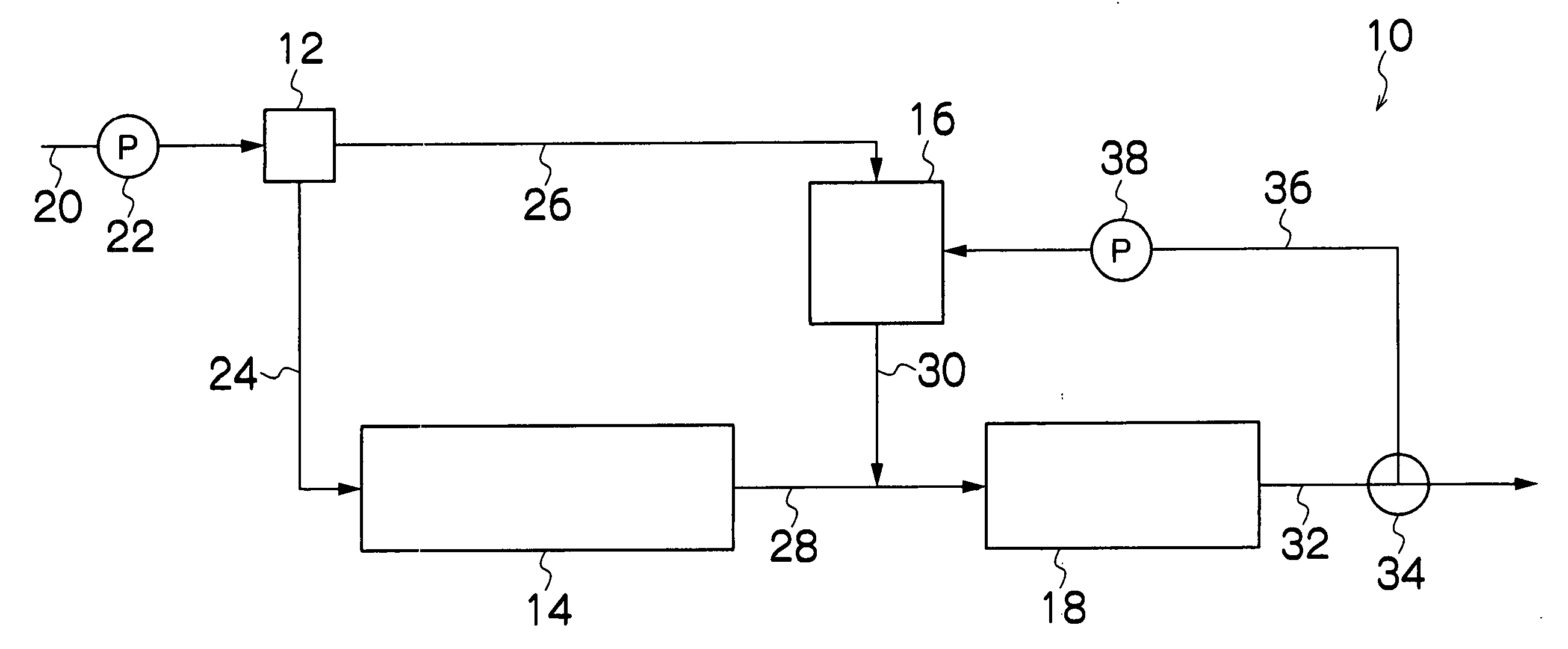
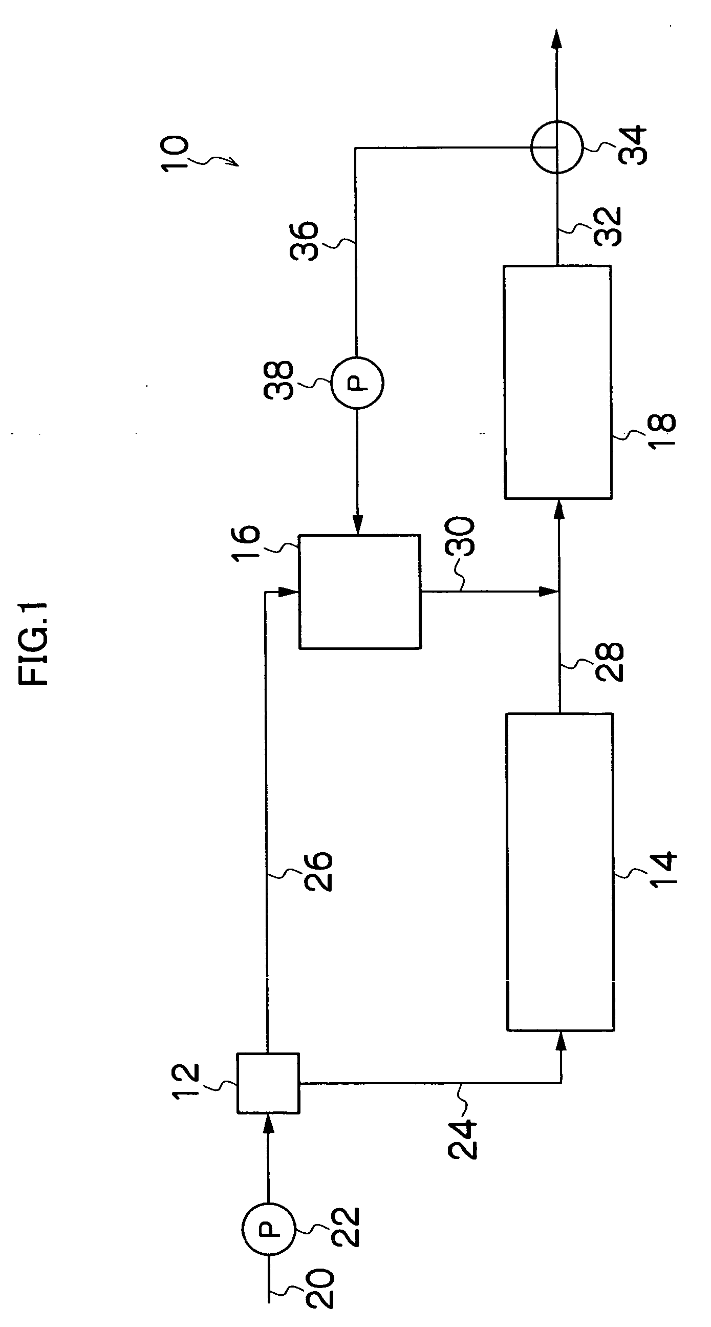
[0062] A test wastewater treatment was performed by use of nitrogen removing apparatus 10 according to the present invention shown in FIG. 1.

(Wastewater Subjected to Test)

[0063] As the wastewater subjected to test, a diluted solution of digested sewage sludge decomposition liquid was used after its ammonium nitrogen concentration (NH4—N) was adjusted to 300 mg / L by adding ammonium sulfate as a NH4—N source. The wastewater thus adjusted had a BOD component concentration of 18 mg / L, and a nitrite (NO2) concentration and a nitrate (NO3) concentration both were 5 mg / L or less.

(Treatment Conditions)

[0064] The distribution ratio by the distributor 12: The first pipe 24 to the second pipe 26=65:35. [0065] The volume load of each of the vessels 14, 16, and 18 was determined based on wastewater concentration (NH4—N)=300 mg / L. The volume load of nitrification vessel 14 was set at 0.6 kg-N / m3 / day. Furthermore, the nitrification vessel 14 was packed with entrapping immobilization pallets,...

example 2

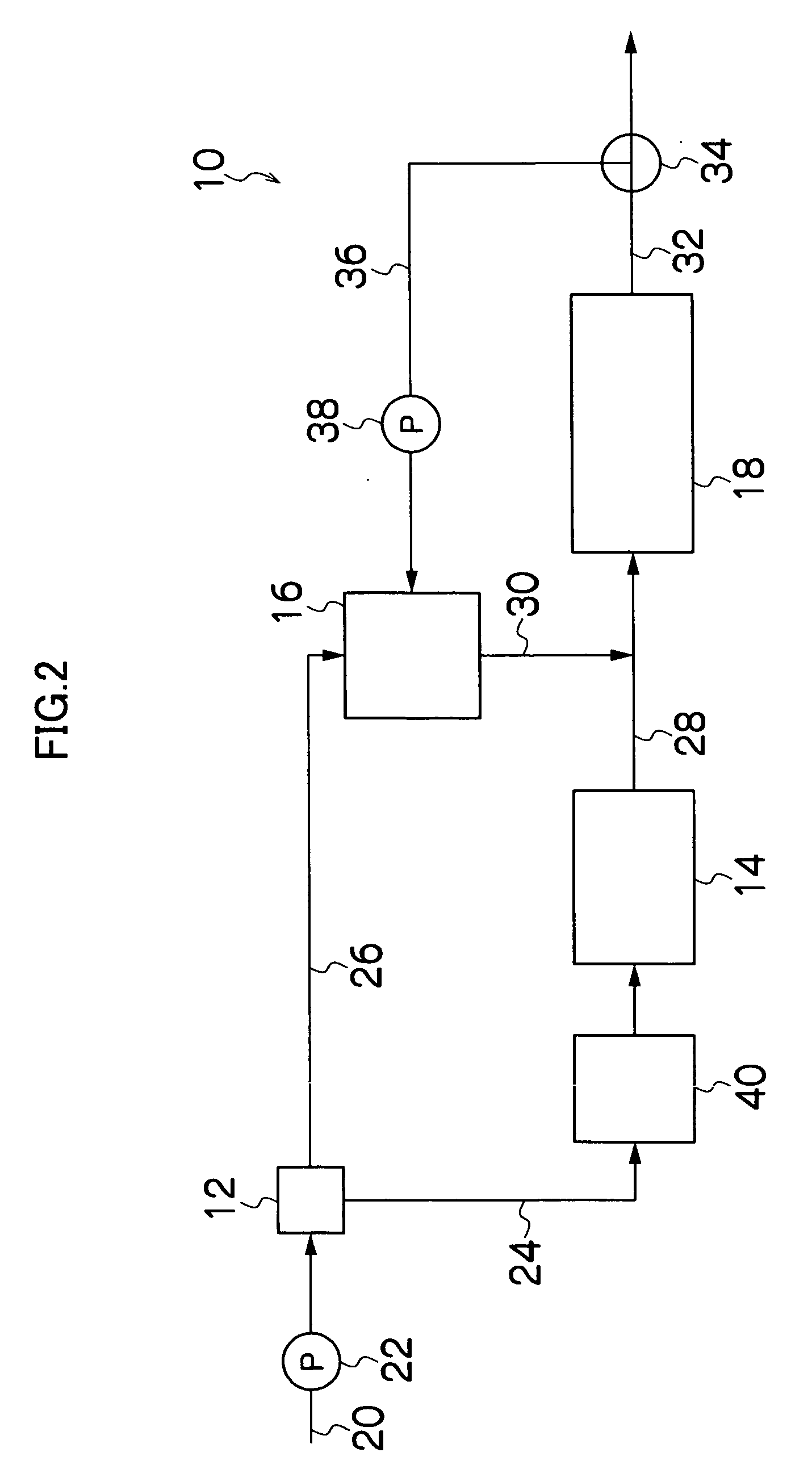
[0073] A test wastewater treatment was performed by use of nitrogen removing apparatus 10 according to the present invention shown in FIG. 2.

(Wastewater Subjected to Test)

[0074] As the wastewater subjected to test, a diluted solution of digested sewage sludge decomposition liquid was used after its ammonium nitrogen concentration (NH4—N) and BOD component concentration were adjusted respectively to 300 mg / L by adding ammonium sulfate as a NH4—N source, and 200 mg / L by adding sodium acetate as a BOD component source. Note that nitrite (NO2) concentration and nitrate (NO3) concentration of the wastewater thus adjusted were 5 mg / L or less.

(Treatment Conditions)

[0075] The distribution ratio by the distributor 12: The first pipe 24 to the second pipe 26=65:35. [0076] The volume load of each of the vessels 14, 16, and 18 was determined based on wastewater concentration (NH4—N)=300 mg / L. The volume load of nitrification vessel 14 was set at 0.6 kg-N / m3 per day. Furthermore, the nitri...

example 3

[0085] A test wastewater treatment was performed by use of nitrogen removing apparatus 10 according to the present invention shown in FIG. 4.

(Wastewater Subjected to Test)

[0086] The same wastewater as used in Example 1 was used.

(Treatment Conditions)

[0087] The distribution ratio by the distributor 12: The first pipe 24 to the second pipe 26=65:35. [0088] The volume load of each of the vessels 14, 16, and 18 was determined based on wastewater concentration (NH4—N)=300 mg / L. The volume load of nitrification vessel 14 was set at 0.6 kg-N / m3 / day. Furthermore, the nitrification vessel 14 was packed with entrapping immobilization pallets, which were previously heated at 60° C. for one hour, to a packing ratio of 15% by volume. [0089] The nitrogen load of the denitrification vessel 16 based on the sum (NOx—N) of nitrite nitrogen (NO2—N) and nitrate nitrogen (NO3—N) was set at 0.2 kg-N / M3 / day. The denitrification vessel 16 was packed with attaching media made of vinyl chloride so as t...


PUM


Abstract

A method of removing nitrogen, in which the nitrogen is removed from wastewater containing a BOD component and ammonium nitrogen by anaerobic ammonium oxidation, comprising the steps of: distributing the wastewater into two portions which are a nitrification vessel and a denitrification vessel at a predetermined distribution ratio; mixing first treated water which is nitrified by ammonium oxidizing bacteria from ammonia to nitrite in the nitrification vessel, with second treated water which is denitrified by denitrification bacteria in the denitrification vessel; and feeding the mixed water to an anaerobic ammonium oxidation vessel to simultaneously denitrify ammonia and nitrite by ammonium oxidizing bacteria, thereby obtaining a third treated water treated in the anaerobic ammonium oxidation vessel, which is then fed back to the denitrification vessel for denitrification and BOD decomposition.

Description

BACKGROUND OF THE INVENTION [0001] 1. Field of the Invention [0002] The present invention relates to a method and apparatus of removing nitrogen, and more particularly, to a method and apparatus of removing nitrogen, in which ammonium nitrogen is removed from wastewater containing a BOD component and ammonium nitrogen by ammonium oxidation. [0003] 2. Description of the Related Art [0004] Nitrogen components contained in sewage and industrial effluent cause eutrophication in lakes and lower the level of dissolved oxygen in rivers. For these reasons, they must be removed. Examples of nitrogen components contained in the sewage and industrial effluent primarily include ammonium nitrogen, nitrite nitrogen, nitrate nitrogen, and organic nitrogen. [0005] Conventionally, when the concentration of nitrogen in such wastewater is low, an ion exchange method and oxidation with chloride or ozone are used to remove nitrogen. When the concentration of nitrogen is medium or high, biological treatm...

Claims


Application Information

Patent Timeline
IPC IPC(8): C02F3/34C02F3/30
CPCC02F3/302C02F2101/166C02F2101/163C02F3/28C02F3/34
Inventor ISAKA, KAZUICHISUMINO, TATSUO
Owner HITACHI LTD
Learn More