Processing apparatus which performs predetermined processing while supplying a processing liquid to a substrate

a processing apparatus and substrate technology, applied in the direction of spray discharge apparatus, conductive pattern formation, electromechanical system manufacture, etc., can solve the problems of reducing the particle diameter of a drop, clogging of the nozzle, and affecting the efficiency of processing, so as to achieve efficient wiring and limited injection capability

Inactive Publication Date: 2005-09-29
NAT INST OF ADVANCED IND SCI & TECH
View PDF7 Cites 48 Cited by
  • Summary
  • Abstract
  • Description
  • Claims
  • Application Information

AI Technical Summary

Benefits of technology

[0006] By the way, using an ink jet nozzle as that described above in the following manner has been proposed. According to this proposed technique, drops of a solder paste are injected directly toward a substrate instead of injecting a resist liquid, and a wiring pattern is formed. When the proposed technique is used, since a wiring pattern is formed directly on a substrate, wiring can be formed efficiently. Meanwhile, although it is increasingly necessary that the diameter of an injection outlet of a nozzle is small as wiring patterns become finer and finer these days, clogging of the nozzle is arising as a big problem. In addition, to the extent that an ink jet nozzle is used, the injection capability is limited. This inevitably reduces the particle diameter of a drop which an ink jet nozzle can stably inject down into a predetermined range. Owing to this, in the case of an apparatus which performs predetermined processing while supplying drops of processing liquid upon a substrate by the ink jet method, drops can be supplied only to a region which is as wide as or wider than the particle diameters of the drops, thus limiting substrates which can be processed.

Problems solved by technology

Meanwhile, although it is increasingly necessary that the diameter of an injection outlet of a nozzle is small as wiring patterns become finer and finer these days, clogging of the nozzle is arising as a big problem.
In addition, to the extent that an ink jet nozzle is used, the injection capability is limited.
This inevitably reduces the particle diameter of a drop which an ink jet nozzle can stably inject down into a predetermined range.
Owing to this, in the case of an apparatus which performs predetermined processing while supplying drops of processing liquid upon a substrate by the ink jet method, drops can be supplied only to a region which is as wide as or wider than the particle diameters of the drops, thus limiting substrates which can be processed.
Further, since the particle diameters of drops are fixed in the conventional apparatus, even when a processing liquid is to be supplied to a region which is sufficiently wider than the particle diameters of drops, the amount of drops injected and supplied from the nozzle to a substrate per unit time is restricted to values which correspond to the particle diameters of drops (i.e., the minimum amount), which serves as a major obstacle against an improvement of the throughput.
Further, although regions of different sizes which are to receive a processing liquid are present even within a single substrate in some cases, that is, there are some substrates which include both fine regions and other regions which are wider than the fine regions, an apparatus as that described above which fixes the particle diameters of drops has difficulty in flexibly adapting to such a substrate.
In other words, when there is only one type of particle diameters of drops of a processing liquid, it is necessary to reduce the particle diameter of drops of the processing liquid in order to supply the processing liquid to a fine region, and this however results in supplying the processing liquid at the small particle diameter even to other regions which are wider than fine regions, whereby the throughput inevitably decreases.
Further, when a substrate includes a smaller processing region than the particle diameter of drops of the processing liquid, it is not possible to process this region.
In the case of the conventional ink jet method (the piezo method or the thermal method) in particular, it is difficult to inject a drop of an extremely small amount below 1 pl (pico liter).
While this has given rise to a demand for an apparatus which is capable of supplying a processing liquid to a substrate as drops which have diameters suitable to a region within the substrate which is to receive the processing liquid, there still is a problem today that the particle diameters of drops are generally fixed and an apparatus is not versatile as described above.

Method used


Image

  • Processing apparatus which performs predetermined processing while supplying a processing liquid to a substrate
  • Processing apparatus which performs predetermined processing while supplying a processing liquid to a substrate
  • Processing apparatus which performs predetermined processing while supplying a processing liquid to a substrate

Examples


first embodiment

[0032] (Forming Fine Line)

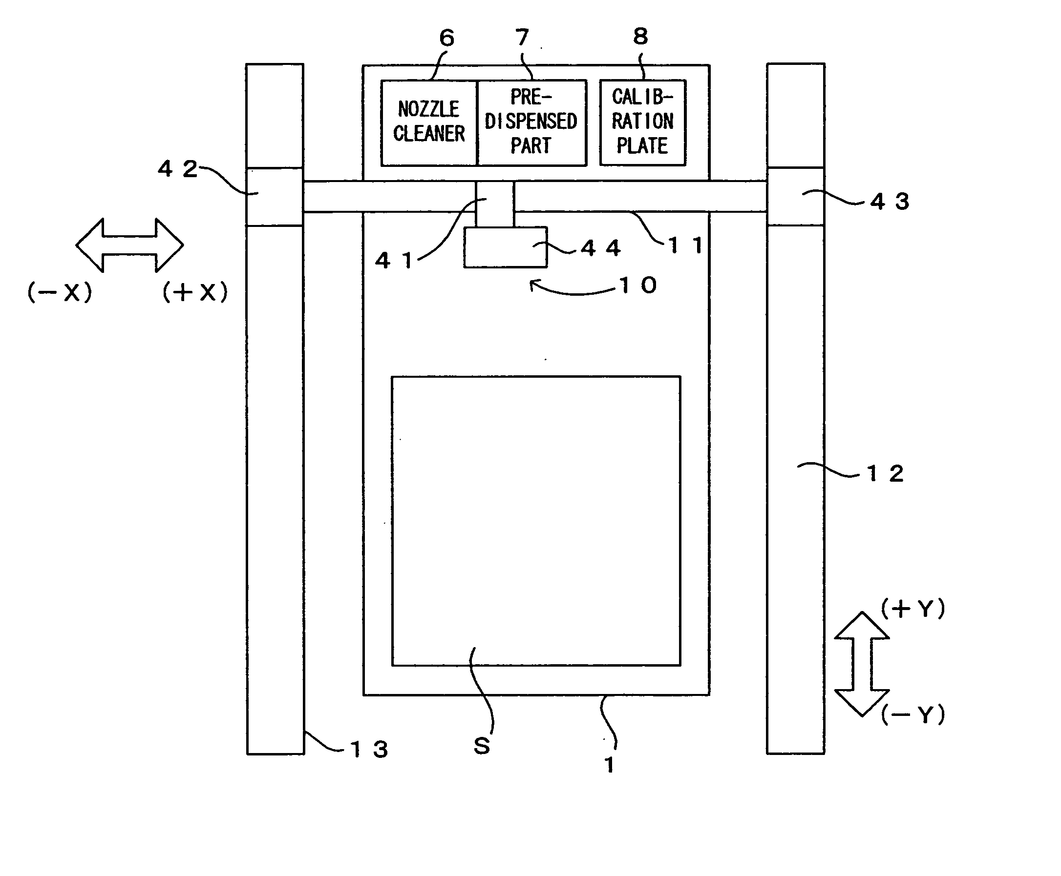
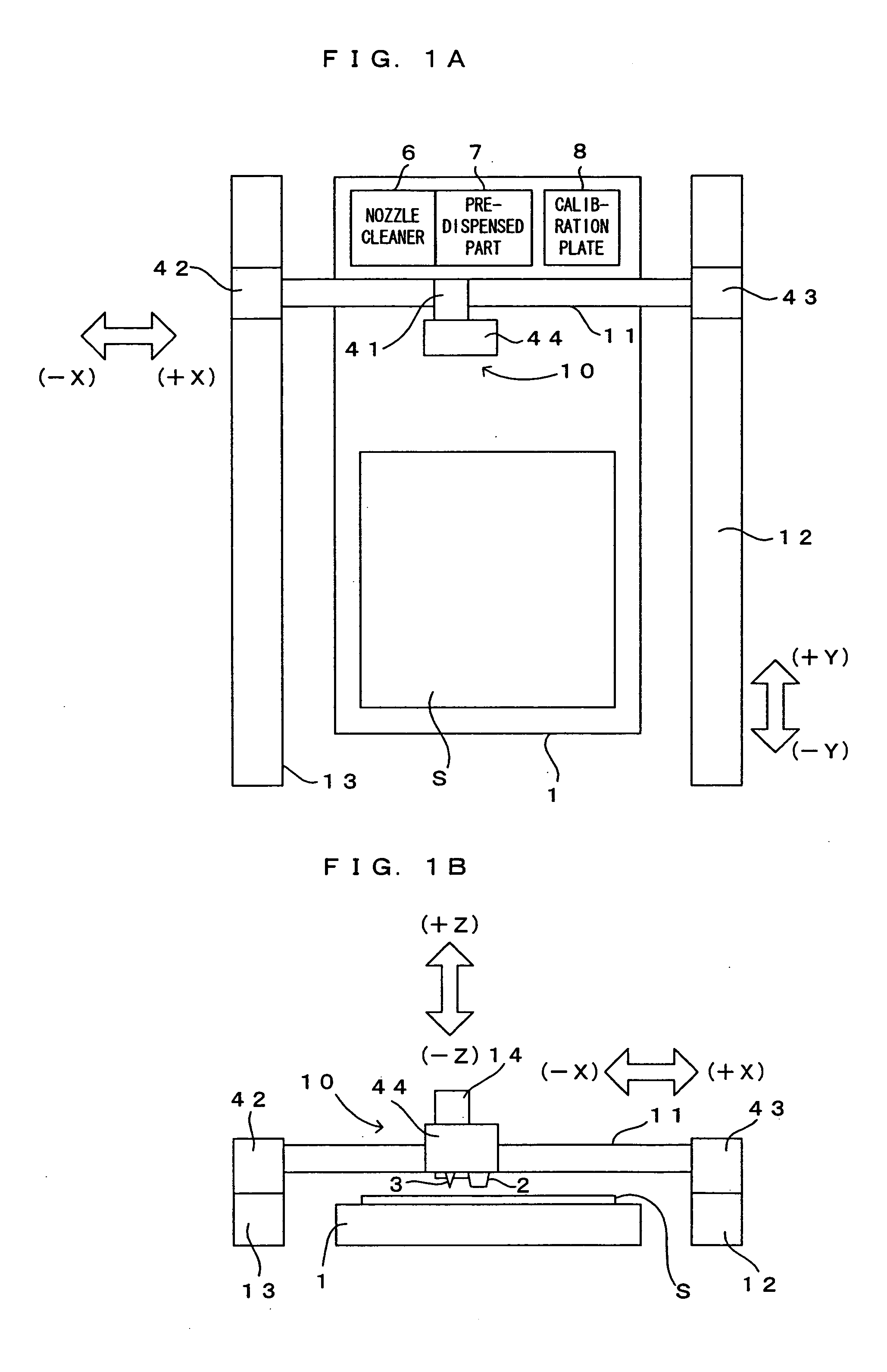
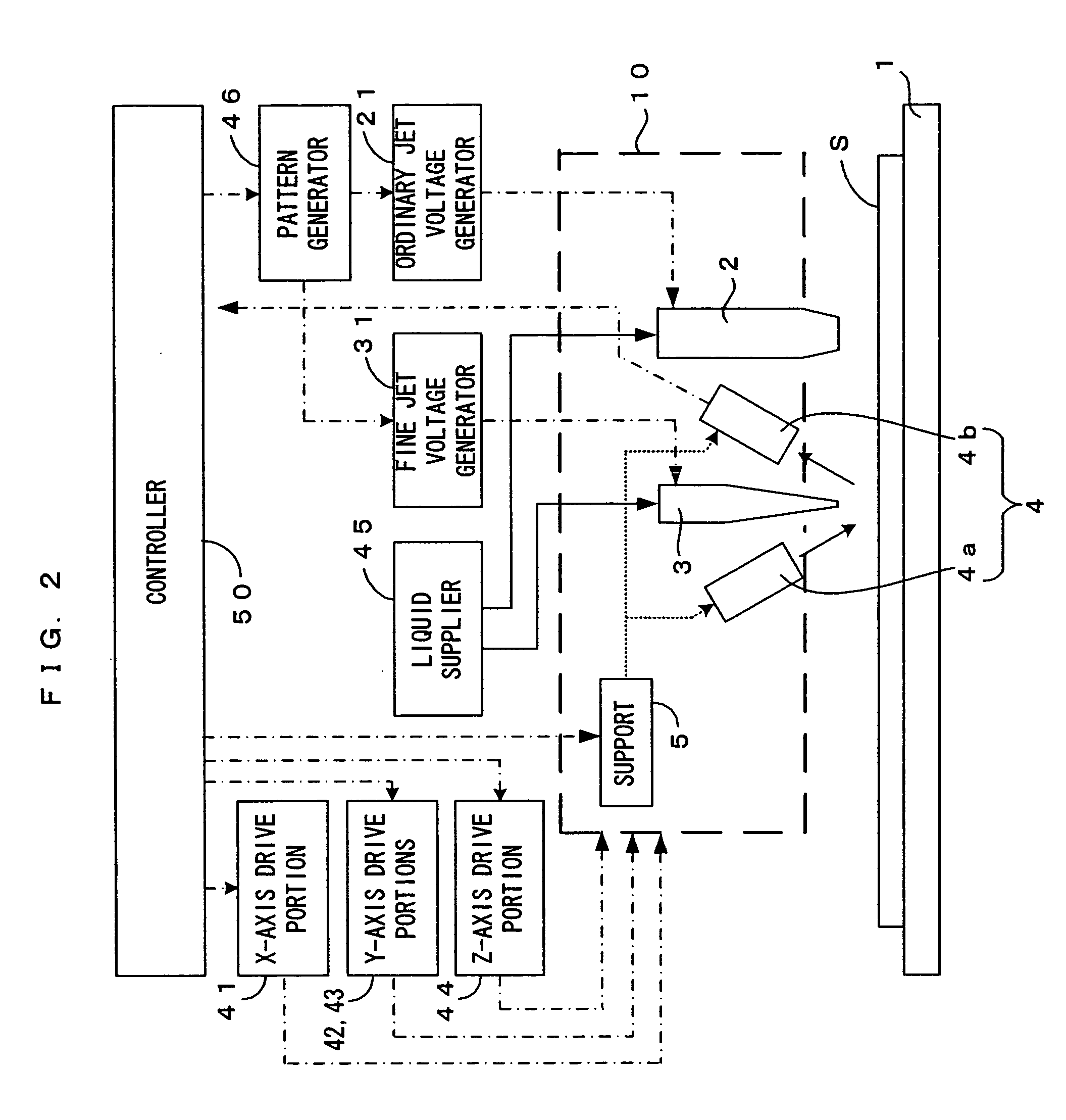
[0033]FIG. 1 is a drawing which shows a first embodiment of a processing apparatus according to the present invention. FIG. 2 is a schematic drawing which shows the electric structure of the processing apparatus of FIG. 1. This processing apparatus is a processing apparatus which forms a predetermined pattern while supplying a metal paste, a colloid solution of fine metal particles or the like (hereinafter referred to simply as a “solution”) as the “processing liquid” of the present invention to a substrate S which is an object-to-be-processed. In this processing apparatus, a substrate holder 1 holds the substrate S, and by means of vacuum suction from a suction groove (not shown) which is formed on the substrate holder 1, the substrate S is fixed. As the substrate holder, a stone faceplate can be used for example. In the first embodiment, the substrate holder 1 thus corresponds to the “substrate holding means.”

[0034] Disposed above the substrate holder 1 ...

second embodiment

[0064] (Manufacturing DNA Microarray)

[0065]FIG. 10 is a drawing which shows the second preferred embodiment of the processing apparatus according to the present invention. This processing apparatus is a processing apparatus which manufactures a DNA micro array while supplying a probe DNA solution (hereinafter referred to as a “DNA solution”) as the “processing liquid” of the present invention to the substrate S which is an object-to-be-processed. A slide glass or an Si wafer is used as the substrate S. Further, to increase the processing efficiency, plural substrates S are arranged on the substrate holder 1. For instance, 20×20 (total 400) substrates S are arranged.

[0066] A DNA micro array referred to here is what is obtained by arranging DNA fragments corresponding to genes of an organism to analyze at a high density as small spots on a substrate. For instance, DNAs taken from an organism are isolated and amplified by the PCR (Polymerase Chain Reaction) method, and DNA solutions ...


PUM

PropertyMeasurementUnit
diameteraaaaaaaaaa
widthsaaaaaaaaaa
diameteraaaaaaaaaa

Abstract

Above a substrate holder 1, an ordinary fluid jet nozzle 2 which is capable of injecting drops of a solution having ordinary particle diameters, a fine fluid jet nozzle 3 which is capable of injecting drops of a solution having fine particle diameters which are smaller than the ordinary particle diameters, and a regular reflection laser displacement gauge 4 are disposed. These are attached on the same plate, thereby forming a head 10. The head 10 freely moves in directions X, Y and Z, as an X-axis drive portion 41, Y-axis drive portions 42 and 43 and a Z-axis drive portion 44 operate in accordance with operation commands received from a controller 50 which controls the apparatus as a whole. It is therefore possible to set the head 10 to a predetermined position on a substrate S which is held by the substrate holder 1. Thus, the respective nozzles supply the solutions to any desired positions the substrate S.

Description

CROSS REFERENCE TO RELATED APPLICATION [0001] The disclosure of Japanese Patent Applications No. 2004-083961 filed Mar. 23, 2004 including specification, drawings and claims is incorporated herein by reference in its entirety. BACKGROUND OF THE INVENTION [0002] 1. Field of the Invention [0003] The present invention relates to a processing apparatus which performs, while supplying a processing liquid, predetermined processing of various types of substrates (hereinafter referred to simply as “substrates”) which are used in apparatuses for manufacturing semiconductors and FPDs (Flat Panel Displays), printed substrate manufacturing apparatuses, apparatuses related to biology (for creating DNA micro arrays, DNA chips, etc.), chemical reaction test machines, etc. [0004] 2. Description of the Related Art [0005] Such conventional processing apparatuses of the ink jet method are known which perform predetermined processing, such as formation of patterns, while injecting processing liquids di...

Claims


Application Information

Patent Timeline
Patent Type & Authority Applications(United States)
IPC IPC(8): B01L3/02G01N33/53B05C5/02C12M1/00C12N15/09C40B40/06C40B60/14G01N35/10G01N37/00H01J9/02H01J49/04H05K3/12
CPCB01J2219/0036B01J2219/00378B01J2219/00659B01J2219/00722B01L3/0268B01L2300/0627H05K2201/09727B01L2400/0439C40B40/06C40B60/14G01N35/1016G01N2035/1041H05K3/125B01L2400/027B25H3/02A47L13/58
Inventor NAKAGAWA, YOSHIYUKIMURATA, KAZUHIRO
Owner NAT INST OF ADVANCED IND SCI & TECH
Why Eureka
Try Eureka