Ultraviolet particle coating systems and processes

a technology of ultraviolet coating and particle coating, applied in the field of particle coating, can solve the problems of environmental, health and cost concerns, common use of solvent or non-solvent in conventional particle coating processes, and prone to agglomeration in conventional liquid spray particle coating processes, etc., to achieve rapid polymerization/curing reaction, wide range of available properties, and rapid creation of tack-free surfaces

Inactive Publication Date: 2005-10-06
NEW JERSEY INSTITUTE OF TECHNOLOGY
View PDF12 Cites 3 Cited by
  • Summary
  • Abstract
  • Description
  • Claims
  • Application Information

AI Technical Summary

Benefits of technology

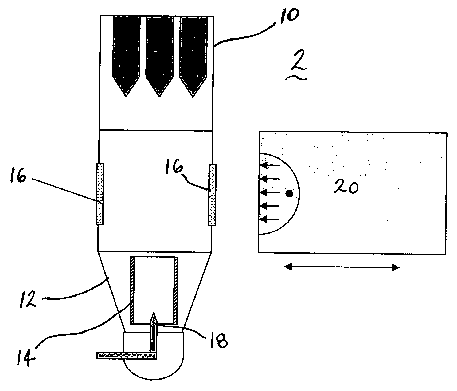
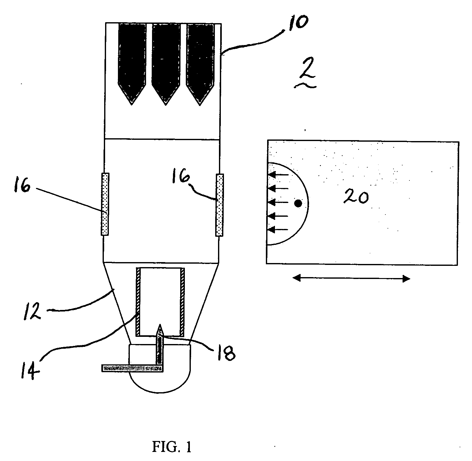
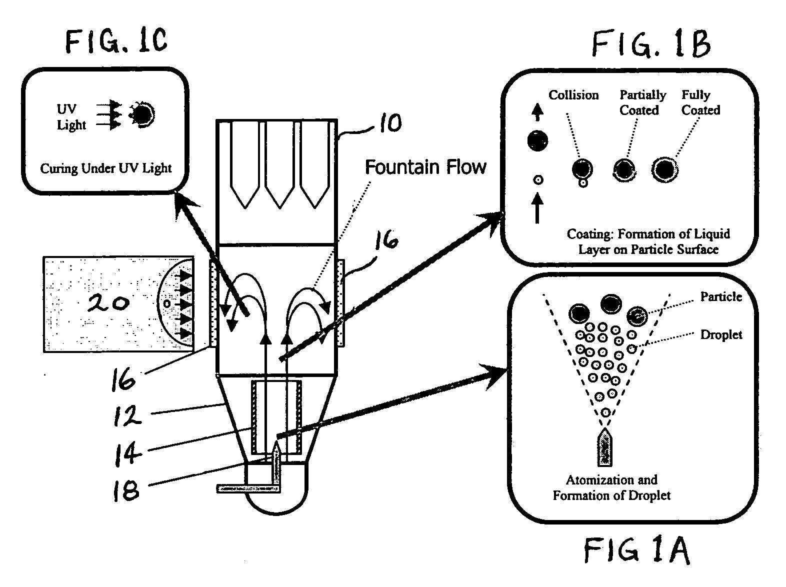
[0004] Novel particle coating processes and systems in accordance with the present invention take advantages of the ability of UV-curable materials to form tack-free surfaces rapidly. By applying UV curable compositions on well suspended particles the present inventors have found that the UV particle coating technology enables a scalable process of coating fine particles at desirable coating thicknesses with a wide spectrum of obtainable properties. Processes in accordance with the present invention completely decouple the particle suspension and film formation steps, enabling ample time to first deliver evenly the coating materials to the particle surfaces, followed by rapid polymerization / curing reaction induced by the UV light to rapidly create tack-free surfaces, thus preventing particles agglomeration while achieving uniform and thin-layer coating. Solventless UV coating processes in accordance with the present invention are considered to be an environmental friendly process since they typically operate at room temperature with very high transfer efficiency. Unlike conventional coating technologies, no heating is required to either evaporate a carrier solvent or cross-link a coating. This is a significant advantage in the coating of heat-sensitive substrates. Final coating performance, such as barrier properties, solubility, permeability, flexibility, chemical resistance, hardness, and sensitivity to stimuli can also be readily tuned to appropriate needs by adjusting the UV chemistry and UV radiation exposure. This technology is readily adoptable to provide functional coatings in various applications including munitions constituents, chemicals, food, pharmaceutical and agricultural industrial sectors.

Problems solved by technology

Conventional liquid spray particle coating processes are commonly known to be prone to agglomeration due to the prolonged period of time needed to convert coated liquid to a tack free solid, even when the uncoated particles can be well separated in the suspension stage.
In addition, the common use of a solvent or nonsolvent in conventional particle coating processes poses environmental, health and cost concerns.

Method used


Image

  • Ultraviolet particle coating systems and processes
  • Ultraviolet particle coating systems and processes
  • Ultraviolet particle coating systems and processes

Examples


experiment i

[0055] Table 5 shows the operating conditions in the coater wherein the curing ratio of Formulation E98C was tested in a coating process. Table 6 lists the sampling procedure. The samples were tested at concentration of UV chemicals at 0.93% and 1.64% vol. Thermo-Gravimetric Analysis (TGA) was employed in the sample analysis. As seen in Table 7 it was observed at about half of the UV chemicals were cured, and elongation in curing time helps to increase the ratio of cured materials

TABLE 5Operational ParametersGap BetweenFluidizationAtomizationPumping flowWurster tubeWeight ofPressurePressurerateand air screenParticle0.4 Bar0.6 Bar0.255 ml / min12 mm210 gAirUV LiquidSecondaryUV ExposureTemperatureper shotAir Pressuretime Per shot25° C.0.273 ml20 psi180 s

[0056]

TABLE 6Sampling during CoatingStep Num.Amount ofConcentration offorAdded UVUV LightUV chemicalsFeedingChemicalsExposure TimeSampling(vol.)10.273 ml30 s + 30 s20.273 ml30 s + 30 s30.273 ml30 s + 30 s40.273 ml30 s + 30 sSample 10.9...

experiment ii

[0058] Table 8 lists the operating conditions in the process. Table 9 shows the sampling procedure. The UV chemical was Formulation E98C. The air screen was modified with a paper filter, in order to adjust the fluidization behavior.

TABLE 8Operating conditionsGap BetweenFluidizationAtomizationPumpingWursterWeight ofPressurePressureflow ratetube and air screenParticle0.66 Bar1.0 Bar0.2 cc / min12 mm230 gAirUV LiquidSecondaryUV ExposureConcentrationTemperatureper shotAir Pressuretime Per shotof UV liquid25° C.0.3 ml20 psi180 s1.4% vol.

[0059]

TABLE 9Amount UVUV lightSpray / Curing StepChemicalsexposure time (s)10.3 ml180 s20.3 ml180 s30.3 ml180 s40.3 ml180 s50.3 ml180 s60.3 ml180 s7360 s

[0060] Now referring to FIGS. 3A-3D and 4A-4D Scanning Electron Microscopy (SEM) with EDX module was employed to determine the coating quality on the surfaces of particles. FIGS. 3A-3D show the SEM pictures of uncoated KCL particles at different magnitudes. It is seen that the particulate surfaces are not s...

experiment iii

[0061] Table 10 lists the operating conditions and Table 11 lists the sampling procedure. The air temperature was raised to 50° C. in this experiment, instead of 25° C. in Experiment II. The UV chemical amount per shot and the UV exposure time were also adjusted in order to shorten the total processing time.

TABLE 10Operating conditionsGap BetweenFluidizationAtomizationPumpingWurster tubeWeight ofPressurePressureflow rateand air screenParticle0.66 Bar1.0 Bar0.2 cc / min12 mm230 gAirSecondaryConcentrationTemperatureAir Pressureof UV liquid50° C.20 psi1.4% vol.

[0062]

TABLE 11Spray / Amount UVUV lightCuring StepChemicalsexposure time (s)10.3 ml180 s20.3 ml180 s30.6 ml180 s40.3 ml360 s50.3 ml360 s

[0063]FIGS. 5A-5D show the SEM pictures of particles coated according to this experiment. The previously non-smooth KCL surface is smooth as a result of coverage with UV chemicals.

[0064] Confocal Raman Spectroscopy was used to check the curing of UV chemicals, as shown in FIG. 6A. FIG. 6A is spect...


PUM

PropertyMeasurementUnit
wavelengthaaaaaaaaaa
timeaaaaaaaaaa
cure timeaaaaaaaaaa

Abstract

Particle coating processes and systems employ UV curable materials to form tack-free surfaces rapidly. By applying UV curable compositions on well suspended particles a UV particle coating technology enables a scalable process of coating fine particles at desirable coating thicknesses with a wide spectrum of obtainable properties. Processes in accordance with the present invention decouple the particle suspension and film formation steps, enabling ample time to first deliver evenly the coating materials to the particle surfaces, followed by rapid polymerization/curing reaction induced by the UV light to rapidly create tack-free surfaces, thus preventing particles agglomeration while achieving uniform and thin-layer coating.

Description

CROSS-REFERENCE TO RELATED APPLICATIONS [0001] This application claims the benefit of U.S. Provisional Patent Application Ser. No. 60 / 557,479, entitled “ULTRAVIOLET PARTICLE COATING PROCESSES,” filed Mar. 30, 2004, the entire disclosure of which is incorporated herein by reference.FIELD OF THE INVENTION [0002] The present invention relates to particle coating and in particular to devices and methods for ultraviolet coating of particles. BACKGROUND [0003] Conventional liquid spray particle coating processes are commonly known to be prone to agglomeration due to the prolonged period of time needed to convert coated liquid to a tack free solid, even when the uncoated particles can be well separated in the suspension stage. In addition, the common use of a solvent or nonsolvent in conventional particle coating processes poses environmental, health and cost concerns. Thus there is a need for a particle coating process that reduces or eliminates agglomeration. It would also be beneficial ...

Claims


Application Information

Patent Timeline
Patent Type & Authority Applications(United States)
IPC IPC(8): B01J2/00B05C5/00B05D1/00B05D1/22B05D3/06C08J3/28
CPCB01J2/006B05D1/005C08J3/28B05D3/067B05D1/22
Inventor YOUNG, MING-WANQIAN, BAINIANGOGOS, COSTASDAVE, RAJESHZHU, LINJIE
Owner NEW JERSEY INSTITUTE OF TECHNOLOGY
Why Eureka
Try Eureka