Optical element and projection exposure apparatus based on use of the optical element

Inactive Publication Date: 2005-10-13
NIKON CORP
View PDF44 Cites 66 Cited by
  • Summary
  • Abstract
  • Description
  • Claims
  • Application Information

AI Technical Summary

Benefits of technology

[0021] the optical element includes a base, and a corrosion resistant film which is formed on at least a part of a surface of the base to avoid corrosion of the base.
[0022] The corrosion resistant film is formed on the surface of the base of the optical element installed to the tip of the projection optical system of the exposure apparatus of the present invention. Therefore, even when the liquid immersion exposure is performed, it is possible to avoid, for example, the corrosion, the erosion, and the dissolution which would be otherwise cause by the contact between the optical

Problems solved by technology

However, if such a situation is continued as it is, it is feared that the depth of focus may be too narrowed and the margin may become insufficient during the exposure operation.
Therefore, inconveniences arise such that the liquid must be supplied again, and it is difficult to recover th

Method used


Image

  • Optical element and projection exposure apparatus based on use of the optical element
  • Optical element and projection exposure apparatus based on use of the optical element
  • Optical element and projection exposure apparatus based on use of the optical element

Examples


second embodiment

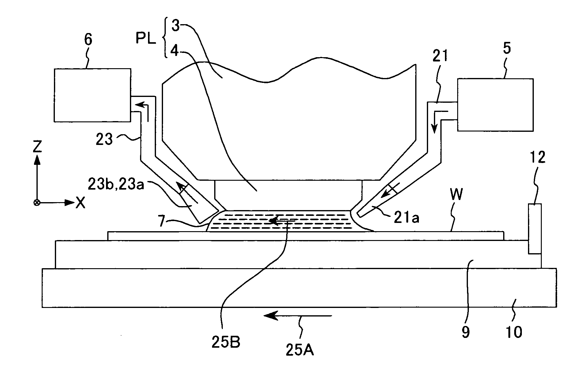
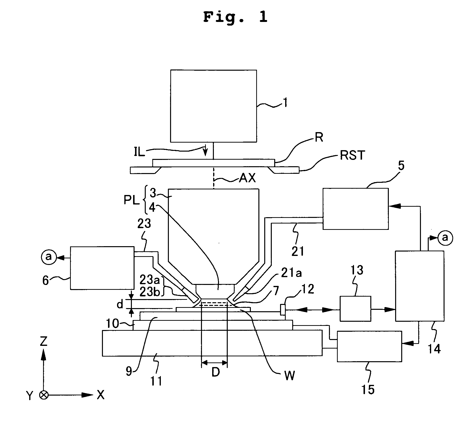
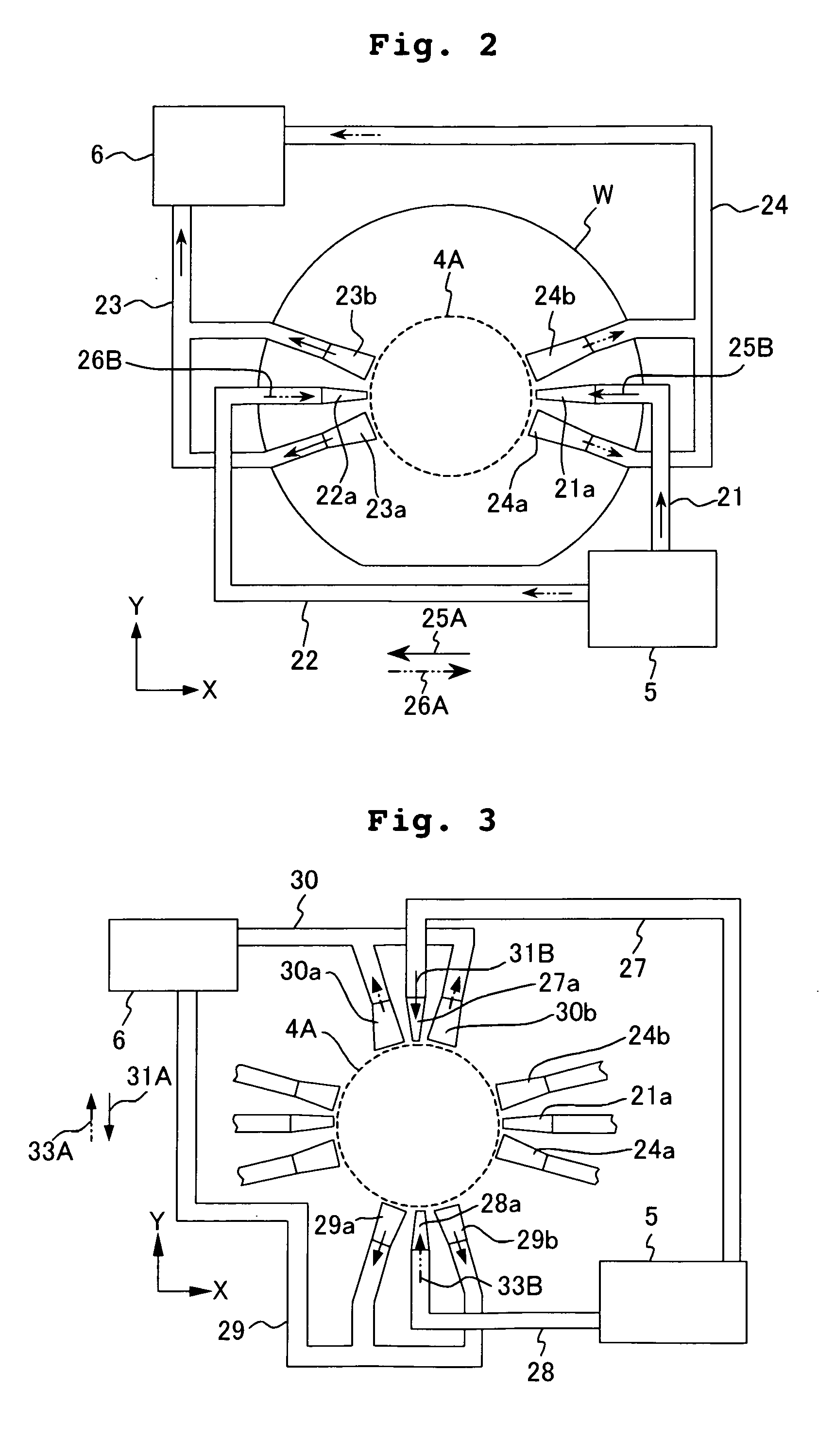
[0044] Next, an explanation will be made with reference to FIGS. 1 to 4 about a second embodiment illustrative of a projection exposure apparatus to which the optical element of the embodiment described above is applied. The projection exposure apparatus of this embodiment is a projection exposure apparatus based on the step-and-repeat system for performing the full field exposure for the shot area on the substrate.

[0045]FIG. 1 shows a schematic arrangement of the projection exposure apparatus of this embodiment. With reference to FIG. 1, the exposure light beam IL, which is composed of an ultraviolet pulse light beam having a wavelength of 193 nm, is radiated from an illumination optical system 1 including, for example, an ArF excimer laser light source as an exposure light source, an optical integrator (homogenizer), a field diaphragm, and a condenser lens. The exposure light beam IL illuminates a pattern provided on a reticle R. The pattern of the reticle R is subjected to the re...

third embodiment

[0063] Next, the present invention will be explained with reference to FIGS. 5 to 7. In this embodiment, the optical element of the embodiment described above is applied to a projection exposure apparatus based on the step-and-scan system.

first embodiment

[0064]FIG. 5 shows a front view illustrating, for example, a lower portion of a projection optical system PLA of the projection exposure apparatus of this embodiment, a liquid supply unit 5, and a liquid recovery unit 6. The same or equivalent constitutive components as those shown in FIG. 4 are designated by the same reference numerals. With reference to FIG. 5, an optical element 32, which is disposed at a lowermost end of a barrel 3A of the projection optical system PLA, has an end portion 32A which is formed so that the end portion has a rectangular shape which is long in the Y direction (non-scanning direction) and which has a necessary portion for the scanning exposure. The optical element 32 is such an optical element that a corrosion resistant film, which is equivalent to that of the optical element produced in the first embodiment, is provided on a fluorite base. During the scanning exposure, a part of a pattern image of the reticle is projected onto a rectangular exposure ...


PUM


Abstract

A liquid immersion exposure apparatus includes a projection optical system (PL) which projects an image of a pattern onto a substrate (W) and a unit (5) which supplies a liquid (7) between an optical element (4) at the end of the projection optical system (PL) and the substrate (W). A corrosion-resistant film composed of an oxide is formed on the surface of the optical element (4) to prevent corrosion by the liquid (7). Consequently, a desired performance of the projection optical system can be secured for a long time even where a full field exposure in the step-and-repeat manner or a scanning exposure in the step-and-scan manner is performed in a liquid-immersion state.

Description

CROSS-REFERENCE [0001] This application is a Continuation Application of International Application No. PCT / JP03 / 015780 which was filed on Dec. 10, 2003 claiming the conventional priority of Japanese patent Application No. 2002-357641 filed on Dec. 10, 2002.BACKGROUND OF THE INVENTION [0002] 1. Field of the Invention [0003] The present invention relates to a projection exposure apparatus which is usable to transfer a mask pattern onto a photosensitive substrate in the lithography step for producing devices including, for example, semiconductor elements, image pickup elements (CCD or the like), liquid crystal display elements, and thin film magnetic heads. In particular, the present invention relates to a projection exposure apparatus based on the use of the liquid immersion method. The present invention also relates to an optical element which is usable for the projection exposure apparatus. [0004] 2. Description of the Related Art [0005] In the production of the semiconductor elemen...

Claims


Application Information

Patent Timeline
IPC IPC(8): G02B21/33G03F7/20
CPCG02B21/33G03F7/70341G03F7/70316G03F7/70958G03F7/70983G03F7/70875
Inventor SHIRAI, TAKESHI
Owner NIKON CORP
Why Eureka
Try Eureka