Small-scale, vital-signs monitoring device, system and method

a monitoring device and vital sign technology, applied in the field of medical devices, can solve the problems of affecting blood pressure, reducing the accuracy of measurement, motion-related artifacts, etc., and achieve the effects of small scale, rapid measurement of health-related indicators, and easy monitoring of this property with minimal discomfor

Inactive Publication Date: 2005-10-13
TRIAGE WIRELESS
View PDF99 Cites 329 Cited by
  • Summary
  • Abstract
  • Description
  • Claims
  • Application Information

AI Technical Summary

Benefits of technology

[0008] The invention has many advantages, particularly in providing a small-scale, low-cost medical device that rapidly measures health-related indicators such as blood pressure, heart rate, and blood oxygen content. The device also integrates with an external glucometer and scale through a connection that is either wired (e.g. serial) or wireless (e.g., Bluetooth, 802.15.4, part-15 radio). The device can also include internal circuitry to measure other indicators, such as a pedometer for measuring steps and calories burned, or a GPS system for measuring total distance traveled.
[0009] The device makes blood pressure measurements without using a cuff in a matter of seconds, meaning patients can easily monitor this property with minimal discomfort. Ultimately this allows patients to measure their vital signs throughout the day (e.g., while at work), thereby generating a complete set of information, rather than just a single, isolated measurement. Physicians can use this information to diagnose a wide variety of conditions, particularly hypertension and its many related diseases.
[0010] The monitor combines all the benefits of conventional blood-pressure measuring devices without any of the obvious drawbacks (e.g., restrictive, uncomfortable cuffs). Its measurement, made with an optical ‘pad sensor’, is basically unobtrusive to the patient, and thus alleviates conditions, such as a poorly fitting cuff, that can erroneously affect a blood-pressure measurement.
[0011] The device additionally includes a simple wired or wireless interface that sends vital-sign information to a persona...

Problems solved by technology

This generates ‘noise’ in the plethysmograph, which in turn can lead to motion-related artifacts in data describing pulse oximetry and heart rate.
Ultimately this reduces the accuracy of the measurement.
Unfortunately, about 20% of all patients ex...

Method used


Image

  • Small-scale, vital-signs monitoring device, system and method
  • Small-scale, vital-signs monitoring device, system and method
  • Small-scale, vital-signs monitoring device, system and method

Examples


Embodiment Construction

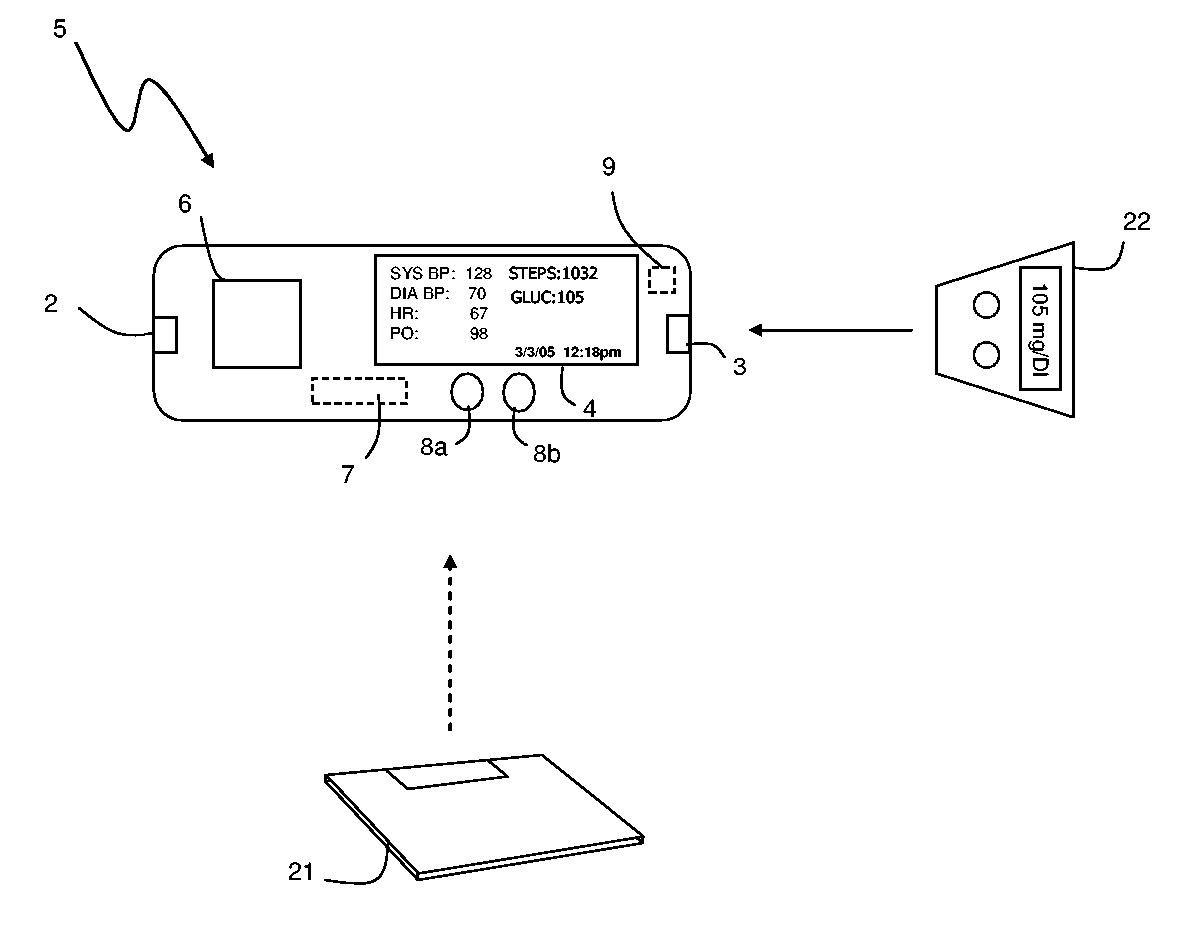
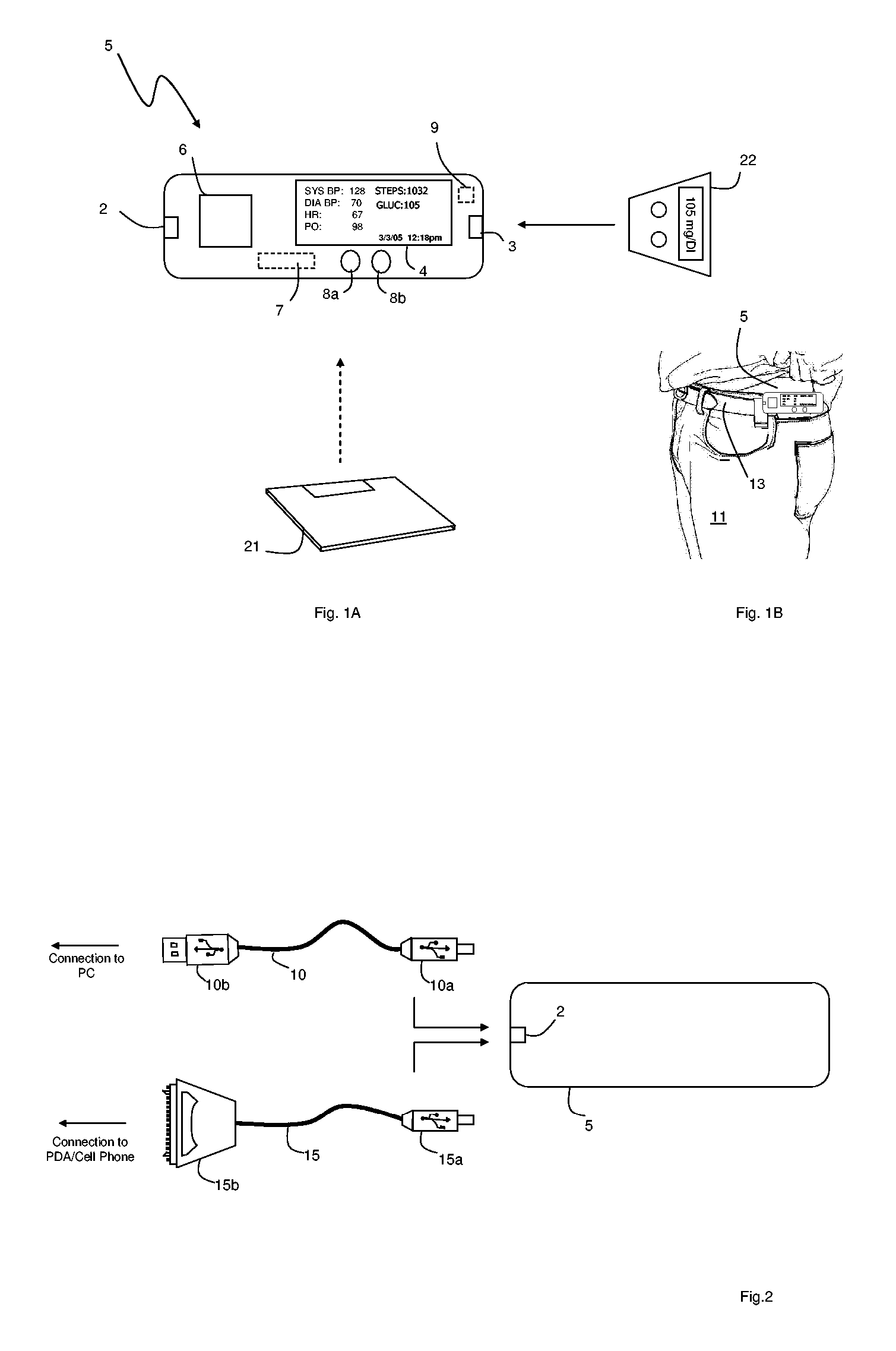
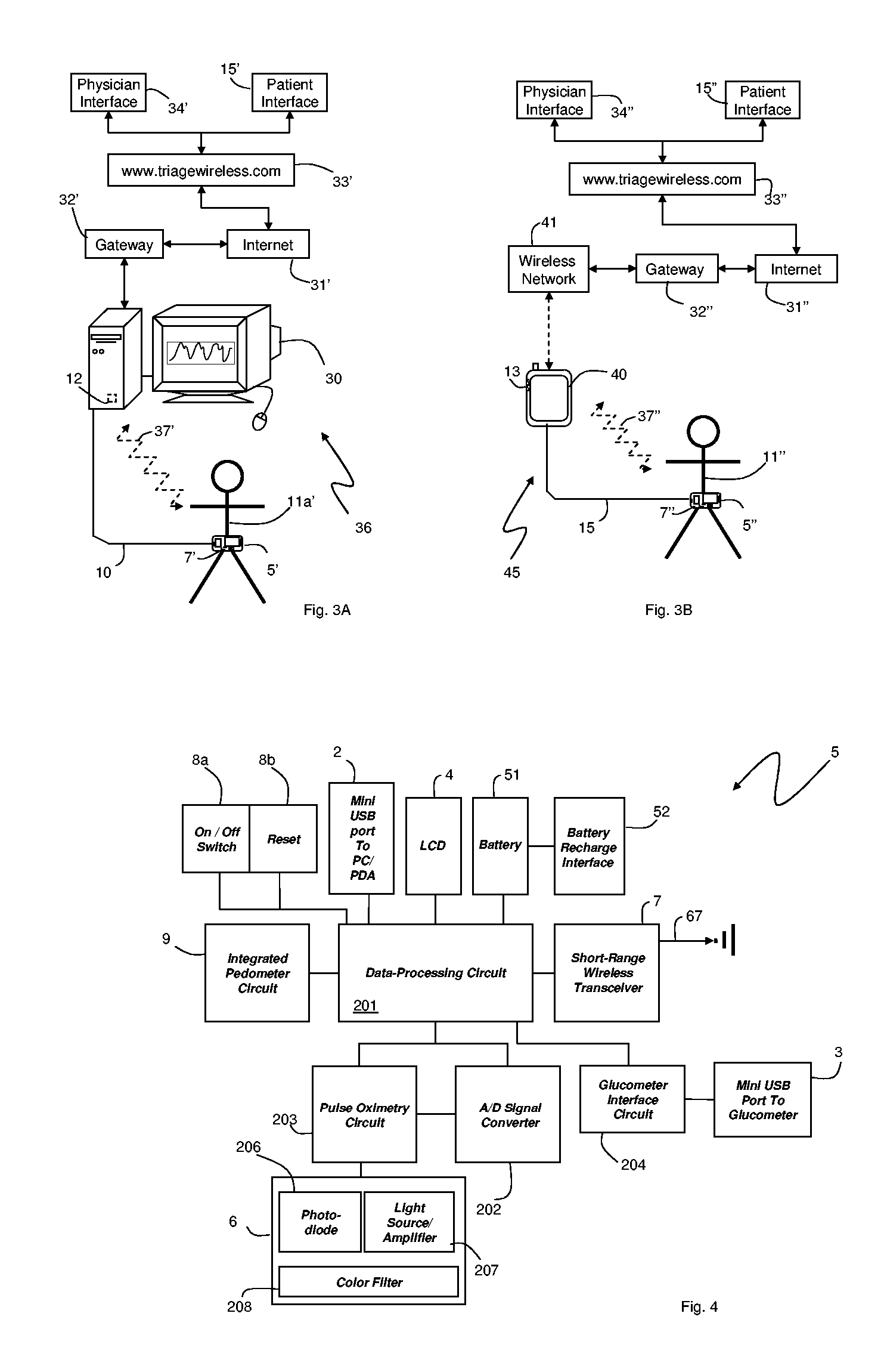
[0018]FIGS. 1A and 1B show a portable, small-scale, vital-sign monitor 5 that measures information such as blood pressure, pulse oximetry, heart rate, glucose levels, calories burned, steps traveled, and dietary information from a patient 11. The monitor 5, typically worn on the patient's belt 13, features: i) an integrated, optical ‘pad sensor’6 that cufflessly measures blood pressure, pulse oximetry, and heart rate from a patient's finger as described in more detail below; and ii) an integrated pedometer circuit 9 that measures steps and, using an algorithm, calories burned. To receive information from external devices, the monitor 5 also includes: i) a serial connector 3 that connects and downloads information from an external glucometer 22; and ii) a short-range wireless transceiver 7 that receives information such as body weight and percentage of body fat from an external scale 21. The patient views information from a liquid crystal display (LCD) display 4 mounted on the monito...


PUM


Abstract

The invention provides a monitoring device featuring: 1) a housing having a first surface; 2) a sensor pad, positioned on the first surface, that includes a first LED emitting red light, a second LED emitting infrared light, and a photodetector; 3) a data-processing circuit that analyzes a signal from the photodetector to generate a blood pressure value; and 4) means for transmitting the blood pressure value to an external device.

Description

CROSS REFERENCES TO RELATED APPLICATION [0001] This application is a continuation-in-part application of U.S. patent application Ser. No. 10 / 709,014, filed Apr. 7, 2004.BACKGROUND OF THE INVENTION [0002] The present invention relates to medical devices for monitoring vital signs such as heart rate, pulse oximetry, and blood pressure. DESCRIPTION OF THE RELATED ART [0003] Pulse oximeters are medical devices featuring an optical module, typically worn on a patient's finger or ear lobe, and a processing module that analyzes data generated by the optical module. The optical module typically includes first and second light sources (e.g., light-emitting diodes, or LEDs) that transmit optical radiation at, respectively, red (λ˜630-670 nm) and infrared (λ˜800-1200 nm) wavelengths. The optical module also features a photodetector that detects radiation transmitted or reflected by an underlying artery. Typically the red and infrared LEDs sequentially emit radiation that is partially absorbed ...

Claims


Application Information

Patent Timeline
IPC IPC(8): A61B5/00A61B5/02A61B5/021G16Z99/00
CPCA61B5/0205A61B5/021A61B5/02438A61B5/1112A61B5/14532A61B2560/0462A61B5/14551A61B5/002A61B5/0022A61B2560/0443A61B5/1455A61B5/02125G16H40/67G16Z99/00
Inventor BANET, MATTHEW JOHN
Owner TRIAGE WIRELESS
Why Eureka
Try Eureka