Nitrogen oxide decomposing element and nitrogen oxide decomposing apparatus including the same

Inactive Publication Date: 2005-10-20
MACHIDA MASATO +1
View PDF4 Cites 22 Cited by
  • Summary
  • Abstract
  • Description
  • Claims
  • Application Information

AI Technical Summary

Benefits of technology

[0010] According to the nitrogen oxide decomposing apparatus of the invention, the nitrogen oxide decomposing apparatus is obtained in which a treatment can be performed at

Problems solved by technology

However, the method proposed in patent document 1 has problems that it is not desirable to use ammonia in consideration for the environment and human body, and further, it is necessary to perform the

Method used


Image

  • Nitrogen oxide decomposing element and nitrogen oxide decomposing apparatus including the same
  • Nitrogen oxide decomposing element and nitrogen oxide decomposing apparatus including the same
  • Nitrogen oxide decomposing element and nitrogen oxide decomposing apparatus including the same

Examples


embodiment 1

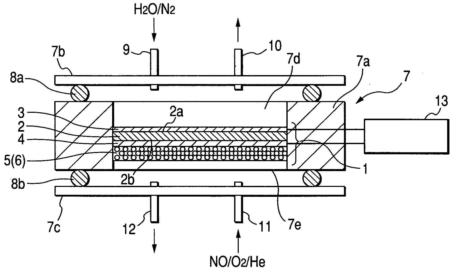
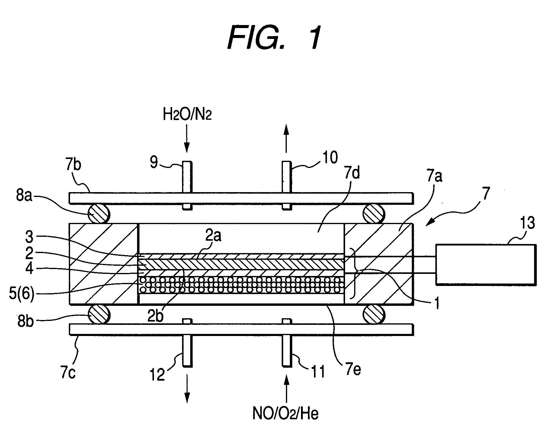
[0020]FIG. 1 is a schematic view showing a nitrogen oxide decomposing element of embodiment 1 of the invention and a structure of a nitrogen oxide decomposing apparatus.

[0021] The nitrogen oxide decomposing apparatus of embodiment 1 includes a nitrogen oxide decomposing element 1 and a frame 7 for housing it. The nitrogen oxide decomposing element 1 includes a conductive solid electrolyte film 2 for selectively allowing a hydrogen ion to pass through, a first electrode layer 3 made of an electronic conductivity base material disposed to be in contact with a part of a surface of the solid electrolyte film 2 and a catalyst (hereinafter referred to as an anodic catalyst) for accelerating anodic oxidation, a second electrode layer 4 made of an electronic conductivity base material disposed to be in contact with the other part of the surface of the solid electrolyte film 2 and a catalyst (hereinafter referred to as a cathodic catalyst) for accelerating cathodic oxidation, and a platinum...

embodiment 2

[0037] A nitrogen oxide decomposing element of embodiment 2 (not shown) is such that a mixed layer including an electronic conductivity base material, a solid electrolyte film, a platinum group catalyst and a cathodic catalyst is disposed between the solid electrolyte film 2 of the nitrogen oxide decomposing element 1 (see FIG. 1) of embodiment 1 and the second electrode 4 and is brought into close contact therewith. This mixed layer can be formed by dispersing aplatinum group catalyst, a cathodic catalyst, a fine-grained electronic conductivity base material, and a fine-grained solid electrolyte film into a solution, heating them to evaporate volatile components, and combining the fine grain components with each other.

[0038] Since the electrochemical reactions described in embodiment 1 occur at an interface between each electrode and the solid electrolyte film, the amount of reaction and the reaction speed are increased in proportion to the area of the interface. In embodiment 2, ...

embodiment 3

[0039]FIG. 6 is a schematic view showing a nitrogen oxide decomposing apparatus of embodiment 3. In the drawings, same or equivalent parts are denoted by the same reference numerals and their description will be omitted. The nitrogen oxide decomposing apparatus in this embodiment includes a nitrogen oxide sensor 14 for detecting the concentration of nitrogen oxide, and a power source / control device 15 for controlling the magnitude of a current flowing between a first and a second current layers 3 and 4 and an energization time in accordance with the concentration of the nitrogen oxide detected by the nitrogen oxide sensor 14. By this, it is possible to control the magnitude of the current flowing through the nitrogen oxide decomposing element 1 and the energization time in accordance with the concentration of the nitrogen oxide. Incidentally, it is desirable that the nitrogen oxide sensor 14 is disposed in the vicinity of a platinum group catalyst 6 supported by a metal oxide 5 at a...


PUM

PropertyMeasurementUnit
Fractionaaaaaaaaaa
Currentaaaaaaaaaa
Currentaaaaaaaaaa

Abstract

A nitrogen oxide decomposing element and a nitrogen oxide decomposing apparatus can perform a treatment at a relatively low temperature without using a material, which is suspected to have influence on the environment and human body, as an oxidant or a catalyst. There is proposed a nitrogen oxide decomposing element 1 including a conductive solid electrolyte film 2 for selectively allowing a hydrogen ion to pass through, a first electrode layer 3 made of an electronic conductivity base material and a catalyst for accelerating anodic oxidation, a second electrode layer 4 made of an electronic conductivity basematerialandacatalystforacceleratingcathodicreduction, and a platinum group catalyst 6 supported by a porous metal oxide 5 disposed to be adjacent to the second electrode layer 4. A low-power consumption nitrogen oxide decomposing apparatus which can efficiently use electric energy is obtained by locating a nitrogen oxide sensor 14 in the vicinity of the platinum group catalyst 6 supported by the metal oxide 5, and controlling the magnitude of a current flowing between the first and the second electrode layers 3 and 4 and the energization time by a power source/control device 15 in accordance with the concentration of nitrogen oxide detected by the nitrogen oxide sensor 14.

Description

TECHNICAL FIELD [0001] The present invention relates to a nitrogen oxide decomposing element for decomposing and removing nitrogen oxide and a nitrogen oxide decomposing apparatus including the same. BACKGROUND ART [0002] A nitrogen oxide purging system for decomposing and removing nitrogen oxide has various uses, such as an exhaust gas treatment of an automobile, a distributed cogeneration system, and air cleaning of an enclosed space such as a long tunnel or a factory, and increased demand is expected into the future. As a conventional technique to remove nitrogen oxide, for example, there is JP-A-2002-153755 as patent document 1. This patent document 1 discloses a method of purging nitrogen oxide NOx by using ammonia as a reductant. There is disclosed that in this method, an ammonia molecule (NH3molecule) donates an electron through an adjacent noble metal to nitrogen monoxide (NO) adsorbed on the noble metal, and as a result, the nitrogen monoxide (NO) becomes apt to dissociate ...

Claims


Application Information

Patent Timeline
IPC IPC(8): B01D53/22B01D53/32B01D53/56B01D53/94
CPCB01D53/56B01D53/326
Inventor MACHIDA, MASATOYAMAUCHI, SHIROKIMURA, MINORUYAMAJI, SHIGERU
Owner MACHIDA MASATO
Why Eureka
Try Eureka