
Microbial biofilm removal methods and systems

Active Publication Date: 2005-11-03
MAYO FOUND FOR MEDICAL EDUCATION & RES
View PDF18 Cites 15 Cited by
  • Summary
  • Abstract
  • Description
  • Claims
  • Application Information

AI Technical Summary

Benefits of technology

[0004] One of the primary issues in accurately treating such infections lies in the specific identification of the microorganism (or microorganisms) in the biofilm. Based on this information, for example, appropriate antimicrobial therapy can be selected. Culturing the microorganisms typically requires that they be removed from the surface of the device in a viable state. Removal that results in loss of microbial viability may lower the sensitivity of a culture-based diagnostic test.
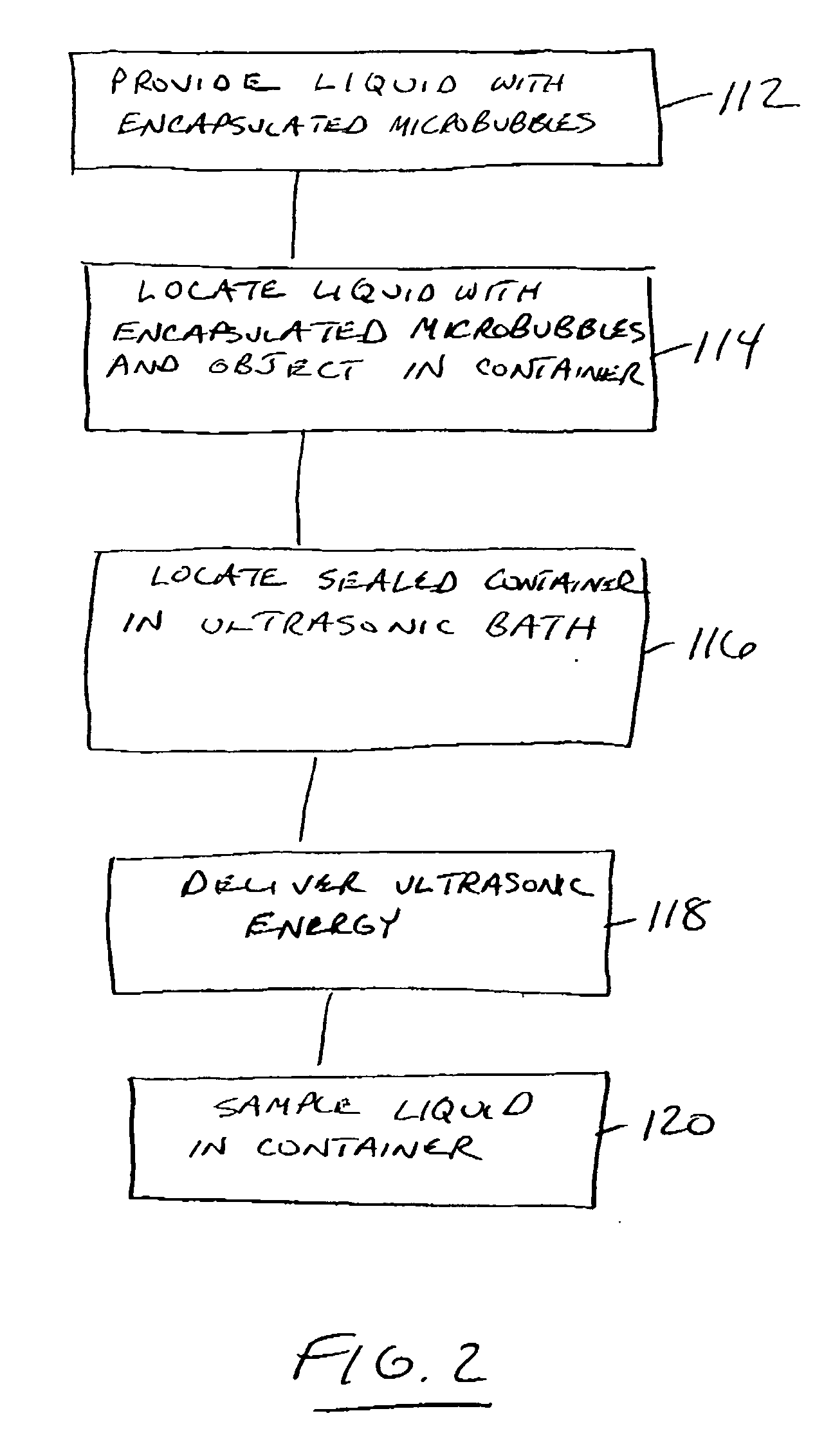
[0010] Although not wishing to be bound by theory, it is postulated that as ultrasound waves radiate through the liquid, they produce high and low pressure areas. In the low pressure phase, microscopic vapor bubbles are formed in the liquid (a process sometimes referred to as cavitation). During the high pressure stage, the microscopic vapor bubbles in the liquid may collapse or implode, releasing an enormous amount of energy on the surface of the object. This agitation may cause a vacuum-scrubbing action by releasing acoustic energy at the surface of the object. Providing microbubbles in the liquid before introducing acoustic energy may supply microbubble cavitation nuclei that enhance the cavitation effect of subsequent sonication.
[0011] Potential advantages of the present invention may include, e.g., improvements in the removal of biofilms from object surfaces, i.e., the present invention may increase the numbers of microorganisms removed from the biofilms. The removal may preferably also retain the viability of a biologically significant portion of the removed microorganisms such that they can be cultured by conventional techniques.
[0012] In those embodiments in which the biofilm removal is performed in a sealed, sterile container, the present invention may also carry a lower risk of microbial contamination than do other removal procedures (scraping, rolling, flushing, rinsing, swabbing, brushing, etc.).

Problems solved by technology

During the high pressure stage, the microscopic vapor bubbles in the liquid may collapse or implode, releasing an enormous amount of energy on the surface of the object.

Method used


Image

  • Microbial biofilm removal methods and systems
  • Microbial biofilm removal methods and systems
  • Microbial biofilm removal methods and systems

Examples


Embodiment Construction

[0023] In the following detailed description of some exemplary embodiments of the invention, reference is made to the accompanying figures of the drawing which form a part hereof, and in which are shown, by way of illustration, specific embodiments in which the invention may be practiced. It is to be understood that other embodiments may be utilized and structural changes may be made without departing from the scope of the present invention.

[0024] In various aspects, the present invention may provide methods, systems and / or kits for the removal of biofilms from one or more surfaces of an object. It may be preferred that the object be a medical device such as a needleless connector, explanted medical device, etc.

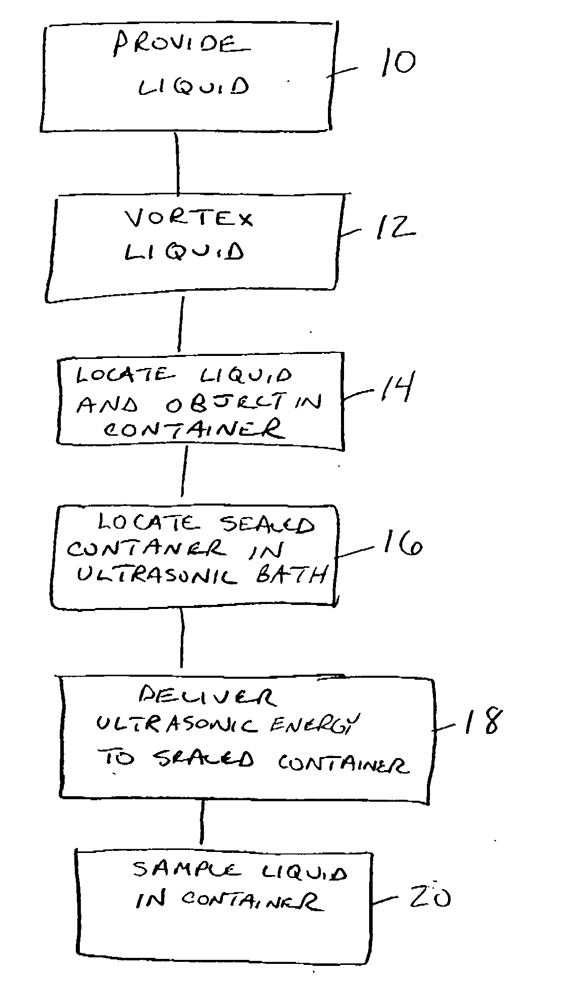
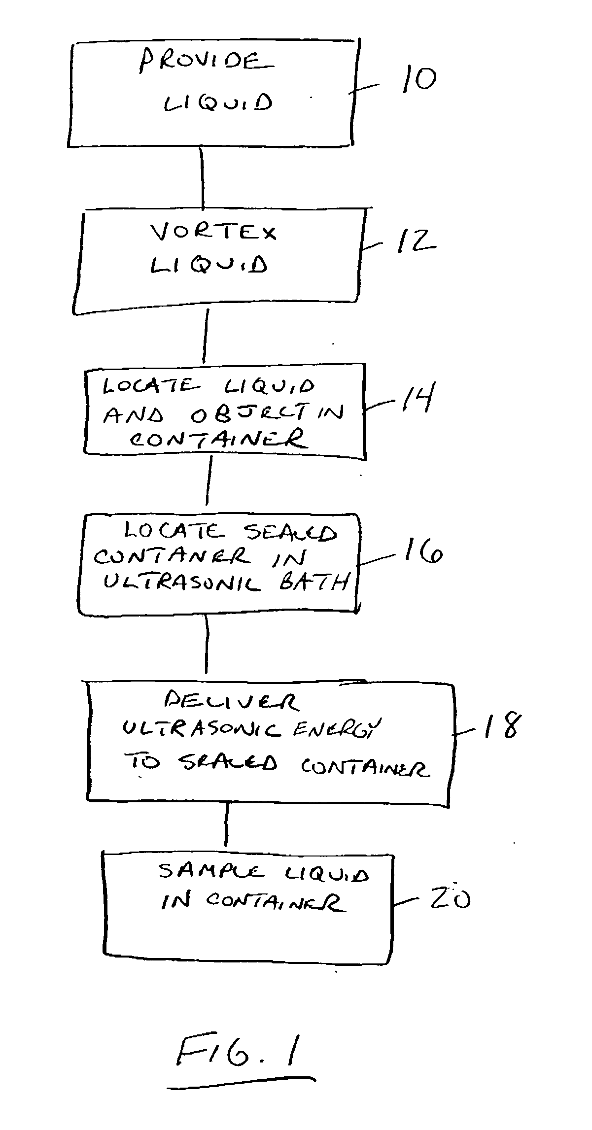
[0025]FIG. 1 is flow chart depicting one exemplary embodiment of the methods of the present invention. The method may optionally include, e.g., removal or explantation of an object such as a medical device. Medical devices processed according to the present invention may in...


PUM

PropertyMeasurementUnit
Pressureaaaaaaaaaa
Energyaaaaaaaaaa
Water insolubilityaaaaaaaaaa

Abstract

Methods, kits, and systems for removing microbial biofilms from surfaces of objects (such as, e.g., explanted medical devices) are disclosed. The methods, kits, and systems rely on the use of acoustic energy in the presence of microbubbles to enhance biofilm removal while retaining viability of the microorganisms in the biofilm. The microbubbles may be provided in a variety of manners such as, e.g., vortexing a liquid, obtaining a suspension that includes pre-formed protein-stabilized microbubbles, etc.

Description

RELATED APPLICATIONS [0001] The present application claims the benefit of U.S. Provisional Application No. 60?554,460, titled MICROBIAL BIOFILM REMOVAL METHODS AND SYSTEMS, filed on Mar. 18, 2004, which is hereby incorporated by reference in its entirety.[0002] The present invention relates to methods, systems, and kits for removing microbial biofilms from surfaces. [0003] Microorganisms commonly attach to surfaces and produce extracellular matrix to form biofilms, the preferred mode of microbial growth in medical, industrial, and natural environments. Growth in biofilms represents a basic survival mechanism by which microorganisms resist environmental influences, antimicrobial killing, and host immune responses. Increased use of indwelling medical devices (e.g., orthopedic devices, neurovascular shunts, prosthetic heart valves, cardiac pacemakers, contact lenses, intrauterine devices, vascular, peritoneal and urinary catheters, etc.) is paralleled by a growing risk of development o...

Claims


Application Information

Patent Timeline
IPC IPC(8): A61L2/02A61L2/025B08B3/10B08B3/12B08B7/02
CPCA61L2/02A61L2/025B08B7/02B08B3/102B08B3/12B08B3/10
Inventor TRAMPUZ, ANDREJPATEL, ROBINGREENLEAF, JAMES F.HANSSEN, ARLEN D.
Owner MAYO FOUND FOR MEDICAL EDUCATION & RES
Learn More