[0012] A particular
advantage of the present invention lies in the ability to lessen or eliminate
reperfusion injury which can result from the rapid restoration of full
blood flow and pressure to ischemic tissue. As described above, the use of thrombolytics and other prior treatments can cause the abrupt removal of an obstruction causing
rapid infusion of blood into the ischemic tissue downstream of the
occlusion. It is believed that such rapid restoration of full
blood flow and pressure, typically at normal physiologic pressures, can result in further damage to the leaky
capillary beds and dysfunctional blood-brain barrier which results from the prior ischemic condition.
[0013] The present invention allows for a controlled reperfusion of the ischemic tissue where blood can initially be released downstream of the obstruction at relatively low pressures and / or flow rates. That is, it will be desirable to initiate the flow of blood or other oxygenated medium slowly and allow the flow rate and pressure to achieve their target values over time. For example, when actively pumping the oxygenated medium, the pumping rate can be initiated at a very low level, typically less than 30 cc / min, often less than 10 cc / min, and sometimes beginning at essentially no flow and can then be increased in a linear or non-linear manner until reaching the target value. Rates of increase can be from 1 cc / min / min to 360 cc / min / min, usually being from 5 cc / min / min to 120 cc / min / min. Alternatively, the flow of blood or other oxygenated medium can be regulated based on pressure as mentioned above. For example, flow can begin with a pressure in the previously ischemic
bed no greater than 10 mmHg, typically from 10 mmHg to 70 mmHg. The pressure can then be gradually increased, typically at a rate in the range from 5-100 mmHg over 2, 8 or even 48 hours. In some instances, it may be desirable to employ blood or other oxygenated medium that has been superoxygenated, i.e., carrying more
oxygen per ml than normally oxygenated blood.
[0014] While pumping will usually be required to achieve and / or maintain adequate
perfusion, in some instances passive
perfusion may be sufficient. In particular,
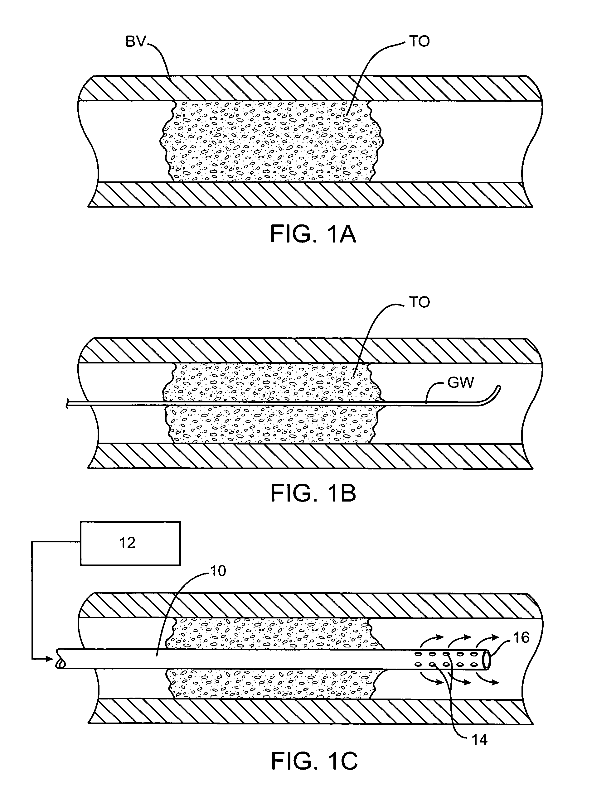
perfusion of the smaller arteries within the cerebral vasculature can sometimes be provided using a perfusion conduit having inlet ports or apertures on a proximal portion of the conduit and outlet ports or apertures on a
distal portion of the conduit. By then positioning the inlet and outlet ports on the proximal and distal sides of the obstruction, respectively, the natural pressure differential in the vasculature will be sufficient to perfuse blood through the conduit lumen past the obstruction. Usually, the inlet ports on the perfusion conduit will be positioned at a location as close to the proximal side of the occlusion as possible in order to minimize the length of perfusion lumen through which the blood will have to flow. In some instances, however, it may be necessary to position the inlet ports sufficiently proximal to the occlusion so that they lie in a relatively patent
arterial lumen to supply the necessary
blood flow and pressure. The cross-sectional area of the perfusion lumen will be maintained as large as possible from the point of the inlet ports to the outlet ports. In this way, flow resistance is minimized and flow rate maximized to take full
advantage of the natural pressure differential which exists.
[0015] While perfusion is maintained through the perfusion conduit, treatment of the
blood vessel blockage may be effected in a variety of ways. For example, thrombolytic,
anticoagulant and / or anti-restenotic agents, such as
tissue plasminogen activator (tPA),
streptokinase,
urokinase,
heparin, or the like, may be administered to the patient locally (usually through the perfusion
catheter) or systemically. In a preferred aspect of the present invention, such thrombolytic and / or
anticoagulant agents may be administered locally to the arterial blockage, preferably through a lumen in the perfusion
catheter itself. Such local administration can be proximal to the
thrombus or directly into the
thrombus, e.g., through side infusion ports which are positioned within the
thrombus while the perfusion port(s) are positioned distal to the thrombus. Optionally, a portion of the blood which is being perfused could be added back to or otherwise combined with thrombolytic and / or
anticoagulant agent(s) being administered through the
catheter. The addition of blood to certain thrombolytic agents will act to augment the desired thrombolytic activity. The availability of the
autologous blood being perfused greatly facilitates such addition. It would also be possible to deliver the agent(s) through the same lumen and distal port(s) as the blood being pumped back through the perfusion lumen so that the agents are delivered distally of the catheter. The latter situation may be used advantageously with neuroprotective agents, vasodilators, antispasmotic drugs,
angiogenesis promoters, as well as thrombolytics, anticoagulants, and anti-restenotic agents, and the like. The two approaches, of course, may be combined so that one or more agents, such as thrombolytic agents, are delivered directly into the thrombus while neuroprotective or other agents are delivered distally to the thrombus. Moreover, such delivery routes can also be employed simultaneously with systemic delivery of drugs or other agents to the patient.
[0016] Alternatively or additionally, mechanical interventions may be performed while the vasculature is being perfused according to the present invention. For example, a perfusion conduit may have a very low profile and be used as a guide element to introduce an interventional catheter, such as an
angioplasty catheter, an
atherectomy catheter, a
stent-placement catheter, thrombus
dissolution device, or the like.
[0017] The perfusion of the oxygenated medium may be performed for a relatively short time in order to relieve
ischemia (which may be advantageous because of damaged capillaries and / or blood-brain barrier) while other interventional steps are being taken, or may be performed for a much longer time either in anticipation of other interventional steps and / or while other long-term interventions are being performed. In particular, when thrombolytic and / or anticoagulant agents are being used to treat the primary blockage, the perfusion can be continued until the blockage is substantially relieved, typically for at least thirty minutes, often for four to eight hours, or even 2-3 days. In other instances, perfusion can be maintained for much longer periods, e.g., more than one week, more than two weeks, more than a month, or even longer. In some cases, it may even be desirable to maintain perfusion and placement of the perfusion conduit for an extended period of time with the patient having a portable or
implantable pump coupled to the conduit. The pump may also have a reservoir for delivery of therapeutic agents and may be implanted or carried on a belt or the like.

