Thermal interface adhesive and rework

a technology of thermal interface and adhesive, which is applied in the direction of semiconductor/solid-state device details, conductors, transportation and packaging, etc., can solve the problems of voids at the interface, excessive heat generation during device operation, and degrade device performan

Inactive Publication Date: 2005-11-17
IBM CORP
View PDF12 Cites 59 Cited by
  • Summary
  • Abstract
  • Description
  • Claims
  • Application Information

AI Technical Summary

Benefits of technology

[0008] The purposes of the present invention have been achieved by providing, according to the present invention, a re-workable conductive adhesive composition comprising an epoxy based conductive adhesive containing conductive metal filler particles dispersed in a solvent-free hybrid epoxy polymer matrix.

Problems solved by technology

This has resulted in excessive heat generation during device operation.
However, it is subject to pump-down and drying which causes voids at the interface.
This degrades the device performance with time due to an increase in interfacial resistance.
However the pre-cut films of these materials are fragile and also have the problem of performance degradation and variability, delamination, bleed-out, out-gasing, and generally require fasteners, clips or screws to hold the PCM in place.
It is generally known that cured coatings of such materials have high intrinsic stress which can cause disruption of interface integrity due to delamination.
This results in increased contact resistance with a corresponding decrease in the heat dissipation effectiveness at the interface.
The commercially available Ag-filled adhesives also have no simple and practical rework method available.
Therefore they cannot be readily removed or reworked from contacting surfaces.
The non-reworkability of these adhesives present a serious drawback in that it does not allow for defect repair or component recovery, recycle or reuse of high cost semiconductor devices, heat sinks and substrates.

Method used


Image

  • Thermal interface adhesive and rework
  • Thermal interface adhesive and rework
  • Thermal interface adhesive and rework

Examples


example 1

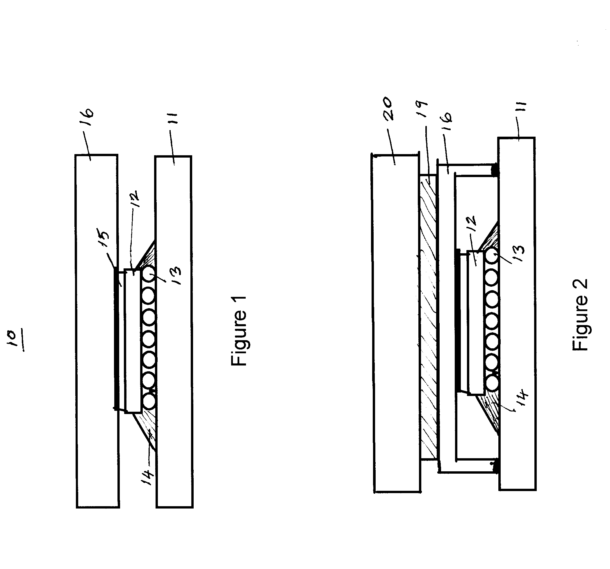
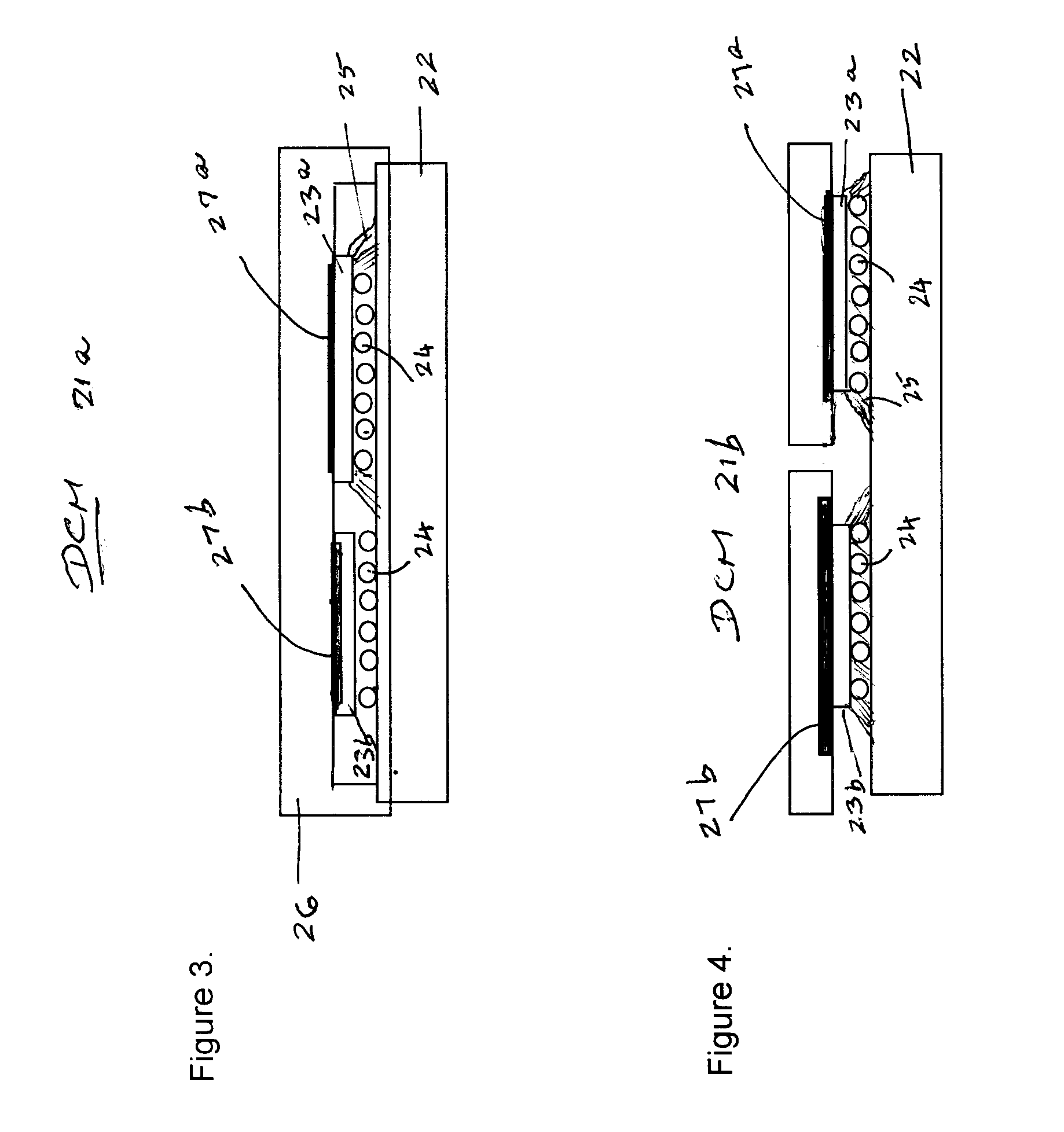
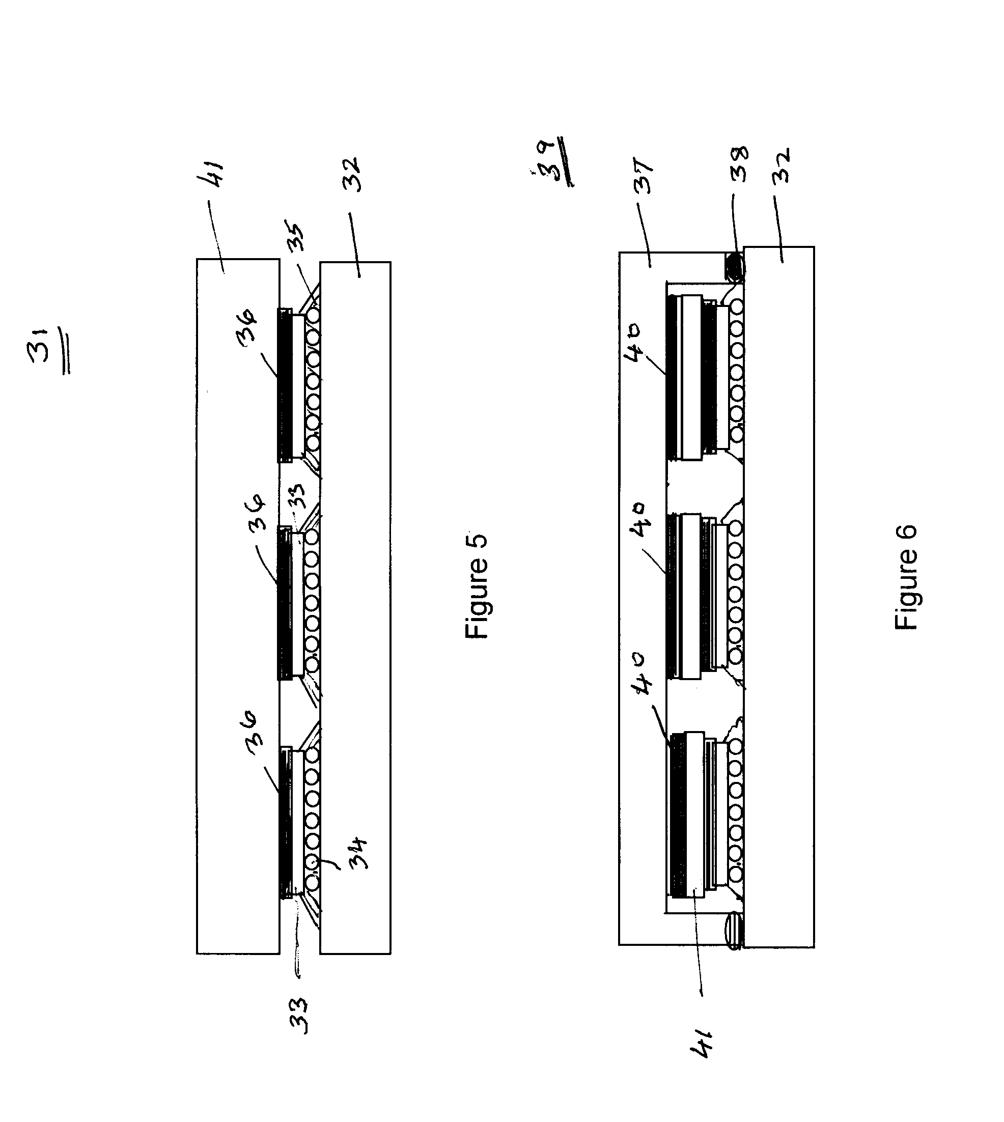
[0069] A soluble mixture of 7.8 g of a 1,3-bis(glycidoxypropyl) tetramethyl disiloxane and 1.3 g poly(n-butylmethacrylate) was prepared by heating with stirring at 70° C., then 2.2 g MeHHPA and 2.5 g HHPA was added and again allowed to stir until a clear mixture was formed. To this mixture was added 0.14 g nonylphenol+0.05 g ethylene glycol, and 0.03 g of the tertiary amine 2,4,6-tris(dimethylamino-methyl) phenol (DMP-30) and thoroughly mixed to form a clear homogeneous blend. About 65.5 g of Au-coated Ag filler were blended in this catalyzed mixture to form screenable conductive adhesive paste having about 82.5 wt % filler loading. The material was characterized for relevant properties and tested as a thermal interface material in conjunction with a SiSiC heat spreader. The data is summarized in table 1.

example 2

[0070] This example was a repeat of Example 1 except that in addition to MeHHPA and HHPA, about 0.2 g of methylnadic anhydride (NMA) was added to the composition described in Example 1. The filler type and % loading were kept the same. Relevant data on the characterization of the cured adhesive derived from this conductive paste are shown in table 1.

example 3

[0071] A soluble mixture of 17.5 g of a 1,3-bis(glycidoxypropyl) tetramethyl disiloxane, and 3.2 g of poly(n-butylmethacrylate) prepared according the method of Example 1. To 7.2 g of this mixture was added 5.5 g DDSA and 0.5 g MA, stirred to dissolve contents, and the catalyst system, 0.1 g nonylphenol and 0.15 g of 2,4,6-tris(dimethylaminomethyl) phenol (DMP-30) were added and thoroughly mixed to form a clear homogeneous blend. To obtain the conductive paste, about 65 g of Ag / Au filler (90% Ag / 10% Au wt % ratio), described in Example 1, was blended in this catalyzed mixture. The material was characterized for relevant properties and tested as a thermal interface material in conjunction with a SiSiC heat spreader. The data is summarized in table 1.


PUM

PropertyMeasurementUnit
particle sizeaaaaaaaaaa
wt %aaaaaaaaaa
temperatureaaaaaaaaaa

Abstract

A reworkable conductive adhesive composition, and method of making such, comprising an epoxy based conductive adhesive containing conductive metal filler particles dispersed in a solvent-free hybrid epoxy polymer matrix. In an additional embodiment an improved method of removing cured conductive polymer adhesives, disclosed here as thermal interface materials, from electronic components for reclamation or recovery of usable parts of module assemblies, particularly high cost semiconductor devices, heat sinks and other module components.

Description

BACKGROUND OF INVENTION [0001] This invention relates to conductive adhesives for the thermal interface between a silicon device and a heat sink / heat spreader in microelectronic assemblies. More particularly, this invention is directed to conductive adhesives with improved functional performance and a method to rework the cured adhesives to allow recovery, recycle, or reuse of the heat sink assembly components without causing any detriment to the device chip or the chip carrier. [0002] The rapid technology advancements in high performance electronics packaging has focused on reduced size and higher operating speed. This has resulted in excessive heat generation during device operation. There is an accompanying need for effective heat dissipation methods to maintain the reliable functional performance of electronic assembly products. The commonly used methods of cooling include helium filled modules, solder thermal interfaces, thermal greases, elastomeric silicone gels, thermoplastic...

Claims


Application Information

Patent Timeline
Patent Type & Authority Applications(United States)
IPC IPC(8): C09D9/00C08K3/08C09J9/02C09J11/04C09J163/00C09J183/06H01B1/00H01B1/22H01B1/24H01L23/373H01L23/42H01L23/433H05K3/32
CPCC08K3/08Y10T428/31515H01L23/42H01L23/433H01L24/32H01L2224/16225H01L2224/73204H01L2224/73253H01L2924/01013H01L2924/01029H01L2924/01033H01L2924/01046H01L2924/01047H01L2924/0105H01L2924/01078H01L2924/01079H01L2924/01082H01L2924/09701H01L2924/16152H01L2924/3011H05K3/321H01L2924/01005H01L2924/01006H01L2924/01019H01L2924/01024H01L2924/01074H01L2924/01075H01L2924/014H01L2924/0132H01L2224/32225H01L23/3737H01L2924/10253H01L2924/15787H01L2224/29111H01L2924/00H01L2924/3512H01L2924/00014H01L2224/32014H01L2224/2612
Inventor SACHDEV, KRISHNA G.BERGER, DANIEL GEORGECHIOUJONES, KELLY MAYDAVES, GLENN GRAHAMTOY, HILTON T.
Owner IBM CORP
Why Eureka
Try Eureka