
Porous fiber

Active Publication Date: 2005-11-24
TORAY IND INC
View PDF2 Cites 50 Cited by
  • Summary
  • Abstract
  • Description
  • Claims
  • Application Information

AI Technical Summary

Benefits of technology

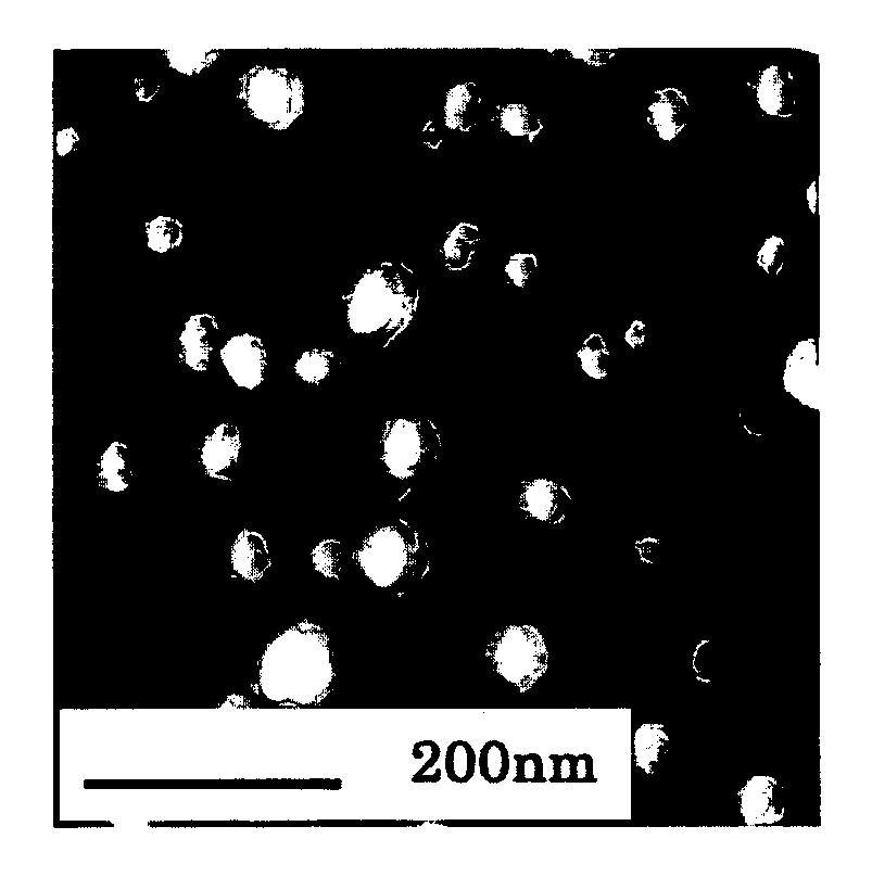
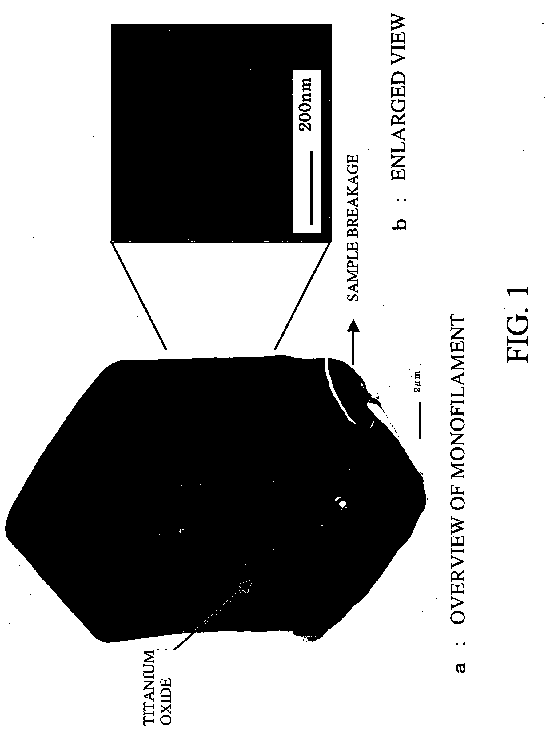
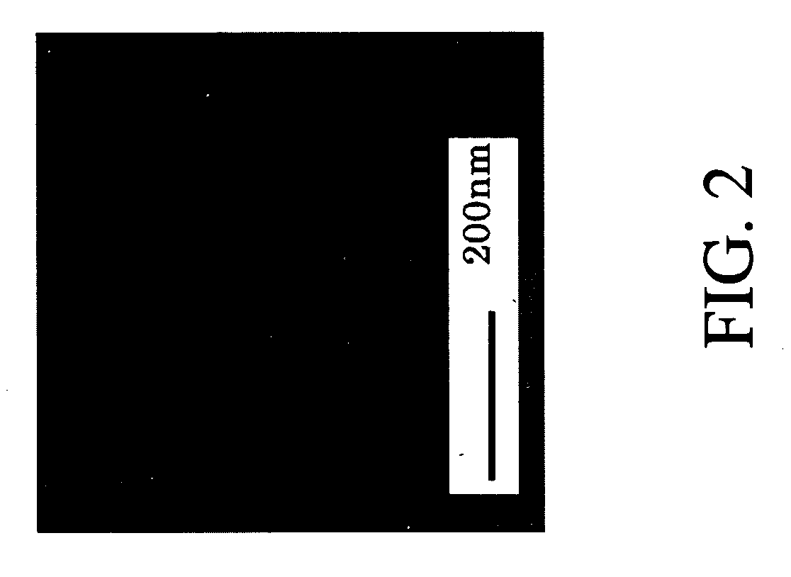
[0030] The porous fibers according to the present invention are substantially free from coarse pores that cannot be avoided in conventional porous fibers. In other words, the porous fibers of the present invention are nanoporous fibers having very homogeneously dispersed nanopores. These nanoporous fibers serve to significantly improve color property as compared with conventional porous fibers to thereby obtain high-value added fibrous articles utilizing excellent moisture adsorption and adsorption properties.

Problems solved by technology

However, in any kind of fibers, fibers each comprising a single polymer have some limitations in the properties thereof.
Attempts have been made to provide hollow fibers having high hollowness, but such hollow portions may be crushed, for example, as a result of false twisting.
In such fibers, the hollow portion generally has a diameter of 1 μm or more, the interface between the polymer and the air in the hollow portion significantly reflects visible radiation, and the resulting fiber cannot satisfactorily develop a color.
However, this fiber shows significantly deteriorated color property.
In actual fact, however, the resulting fiber also shows significantly deteriorated color property, since the blend fiber contains coarsely aggregated PET particles, and the aggregated particles are dissolved off to form coarse pores each having a size on the order of submicrometers to one micrometer.
These fibers, however, show a large variation in size of dispersed particles of PET in the nylon, for example, about 0.1 to 1 μm and cannot improve decreased color property caused by coarse pores.
Thus, the porous fiber does not sufficiently exhibits advantages of the pores.
The fiber, however, invites unstable spinning to thereby obtain yarns with large unevenness and lacks practical utility, because PEI is dispersed as particles in the fiber.
In an experiment for corroboration, the resulting polymer alloy fiber has a strength less than 1.5 cN / dtex and is not usable in practice.
The resulting yarn, however, has a strength less than 0.5 cN / dtex and is not practically usable from this viewpoint of strength, because both PEI and the copolyester have been hydrolyzed in the fiber.

Method used


Image

  • Porous fiber
  • Porous fiber
  • Porous fiber

Examples


example 1

[0288] A N6 (80% by weight) and a copolymerized PET (20% by weight) were melted and kneaded in a twin-screw extrusion-kneader at 260° C. to obtain polymer alloy pellets. The N6 had a relative viscosity of 2.15, a melt viscosity of 274 poises (280° C. at a rate of shear of 2432 sec−1), a melting point of 220° C., and an amount of terminal amino groups of 5.0×10⁻⁵ molar equivalent per gram as a result of blocking amine terminals with acetic acid. The copolymerized PET had an intrinsic viscosity of 0.60, a melt viscosity of 1400 poises (280° C. at a rate of shear of 2432 sec−1) and a melting point of 250° C., had been copolymerized with 5% by mole of 5-sodiosulfoisophthalic acid and contained 0.05% by weight of titanium oxide.

[0289] The transmission electron micrograph of a cross section of the polymer alloy pellets is shown in FIG. 5. The copolymerized PET as islands had diameters in terms of circle of 20 to 30 nm (average diameter of dispersed particles of 26 nm) and were substantia...

example 2

[0309] The N6 and the copolymerized PET were subjected to melt-kneading by the procedure of Example 1, except for blending 95% by weight of N6 and 5% by weight of the copolymerized PET. The kneaded product was subjected to melt spinning and draw false-twisting by the procedure of Example 1, except for changing the discharge rate per one orifice and the number of spinneret orifices, to obtain a 90 dtex, 34-filament crimped polymer alloy yarn. The yarn could be satisfactorily spun without any yarn breaking during continuous spinning for 24 hours.

[0310] The resulting highly oriented undrawn yarn had excellent properties including a strength of 2.7 cN / dtex and a U % of 0.8%. The yarn showed good processability without any yarn breaking in the draw false-twisting process. The crimped yarn had a high bulkiness in terms of a CR of 45% and exhibited excellent crimping quality with satisfactory untwisting. The cross section of the resulting crimped polymer alloy yarn was observed under a TE...

example 3

[0313] The N6 and the copolymerized PET were subjected to melt-kneading by the procedure of Example 1, except for blending 90% by weight of N6 and 10% by weight of the copolymerized PET. The kneaded product was subjected to melt spinning and draw false-twisting by the procedure of Example 1, except for changing the discharge rate per one orifice and the number of spinneret orifices, to obtain a 90 dtex, 34-filament crimped polymer alloy yarn. The yarn could be satisfactorily spun without any yarn breaking during continuous spinning for 24 hours. The resulting highly oriented undrawn yarn showed excellent properties including a strength of 2.7 cN / dtex and a U % of 0.8%. The yarn showed good processability without any yarn breaking in the draw false-twisting process. The crimped yarn had a high bulkiness in terms of a CR of 40% and exhibited excellent crimping quality with satisfactory untwisting.

[0314] The cross section of the crimped polymer alloy yarn was observed under a TEM and ...


PUM

PropertyMeasurementUnit
Weightaaaaaaaaaa
Weightaaaaaaaaaa
Fractionaaaaaaaaaa

Abstract

The present invention provides a nanoporous fiber being substantially free from coarse pores and having homogeneously dispersed nanopores, unlike conventional porous fibers. A porous fiber has pores each having a diameter of 100 nm or less, in which the area ratio of pores each having a diameter of 200 nm or more to the total cross section of the fiber is 1.5% or less, and the pores are unconnected pores, or a porous fiber has pores each having a diameter of 100 nm or less, in which the area ratio of pores each having a diameter of 200 nm or more to the total cross section of the fiber is 1.5% or less, the pores are connected pores, and the fiber has a strength of 1.0 cN / dtex or more.

Description

TECHNICAL FIELD [0001] The present invention relates to a porous fiber which has a multitude of fine and even-sized nanopores and is substantially free from coarse pores that reflect visible radiation. It also relates to a polymer alloy fiber serving as a precursor of the porous fiber in the production thereof, and to a method for producing the polymer alloy fiber. [0002] In the following descriptions relating to the present invention, the term “nanopores” means fine pores each having a diameter of 100 nm or less. [0003] The term “nanoporous fiber” used in the present invention refers to a fiber containing one or more pores having a diameter of 100 nm or less per square micrometer at cross section of a fiber perpendicular to the axial direction thereof. [0004] The fiber relating to the present invention has such a multitude of fine pores and thereby exhibits dramatically increased liquid adsorptivity and / or gas adsorptivity. [0005] To achieve these properties satisfactorily, key fac...

Claims


Application Information

Patent Timeline
IPC IPC(8): B29C48/40D01D5/247D01F6/00D01F6/04D01F6/06D01F6/16D01F6/60D01F6/62D01F6/76D01F6/84D01F8/12
CPCD01D5/247Y10T428/2973D01F6/04D01F6/06D01F6/16D01F6/60D01F6/62D01F6/76D01F6/84D01F8/12B29C47/362Y10T428/2931Y10T428/2924Y10T428/2975Y10T428/2967Y10T428/2935Y10T428/2913Y10T428/2929D01F6/00B29C48/362Y10T442/444Y10T442/3146Y10T442/637Y10T442/3089Y10T442/609Y10T442/64Y10T442/431Y10T442/3163Y10T442/3065B29C48/40C08L23/00B29B7/46B82Y40/00
Inventor OCHI, TAKASHIKISHIRO, AKIRANONAKA, SHUICHIMIHARA, TAKAAKISUZUKI, NORIO
Owner TORAY IND INC
Learn More