Method of dispersing hydrocarbon foulants in hydrocarbon processing fluids
a hydrocarbon processing fluid and foulant technology, applied in the direction of liquid carbonaceous fuels, hydrocarbon oil treatment, corrosion/fouling inhibition of treatment apparatus, etc., can solve problems such as inefficient reaction, and achieve the effects of reducing the overhead entrainment of heavier components, low vapor pressure, and high solvency
- Summary
- Abstract
- Description
- Claims
- Application Information
AI Technical Summary
Benefits of technology
Problems solved by technology
Method used
Image
Examples
example 1
[0062] Quench water, light hydrocarbon and foulant samples are collected from the quench water drum separator of a southern U.S. ethylene plant. Approximately 5 grams of foulant are smeared along the bottom of a two ounce glass bottle and approximately 30 mL of quench water is added to the jar. A control sample is set up along with a test sample. Five mL of dimethyl phthalate (“DMP”) are added to the test bottle, and both bottles are gently shaken. The dimethyl phthalate quickly reduces the viscosity of the foulant. The dimethyl phthalate also remains in the bottom of the bottle as expected based on its density.
example 2
On-Site Testing.
[0063] Testing as described in Example 1 is also conducted at the ethylene plant on fresh samples. During this testing, dimethyl phthalate, when combined in the customer's heavy aromatic distillate (HAD) solvent, did an excellent job at dispersing tars, asphaltenes and coke fines and keeping the foulant suspended in the stream.
example 3
Ethylene Plant On-Line Cleaning Trial.
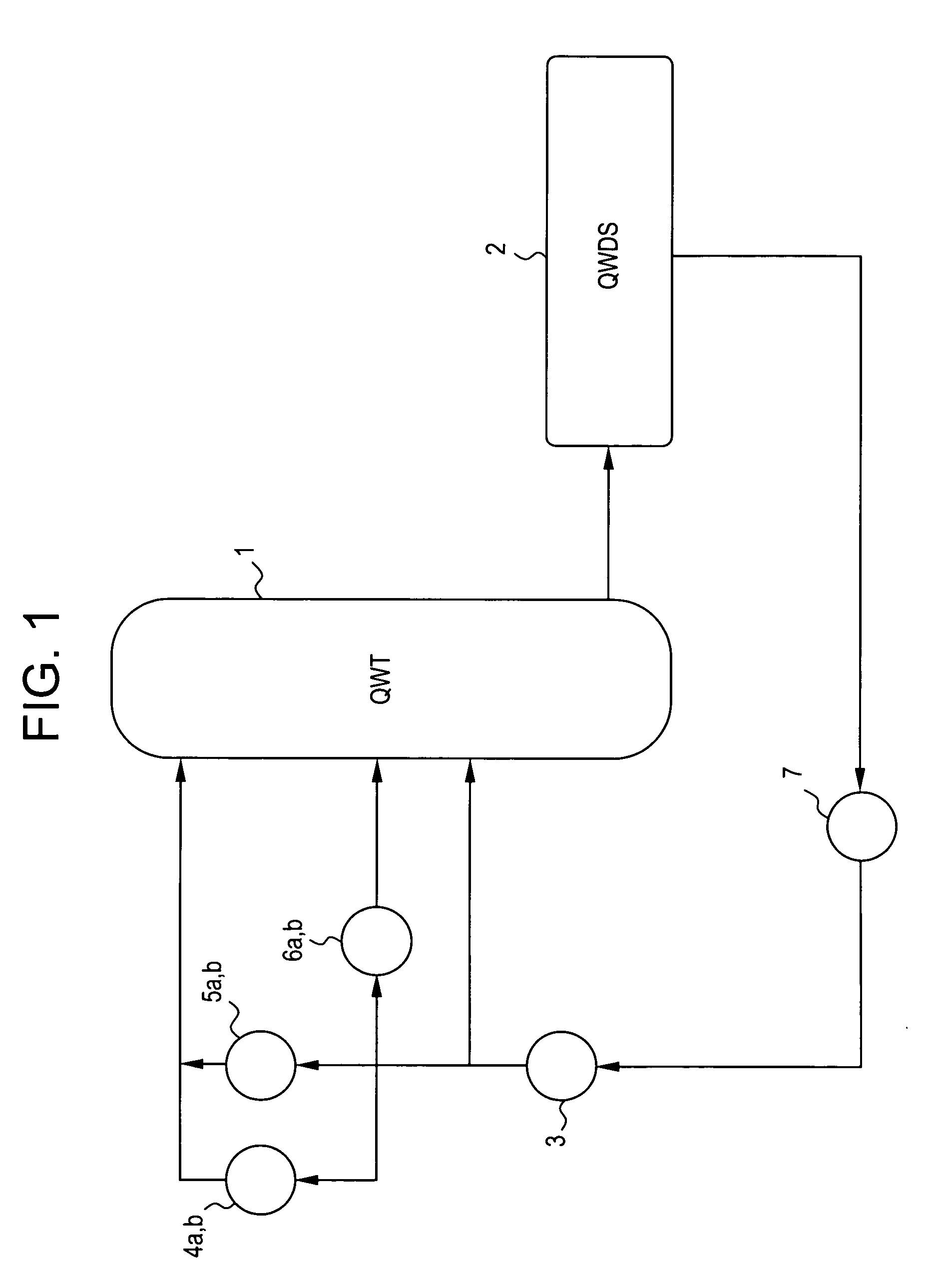
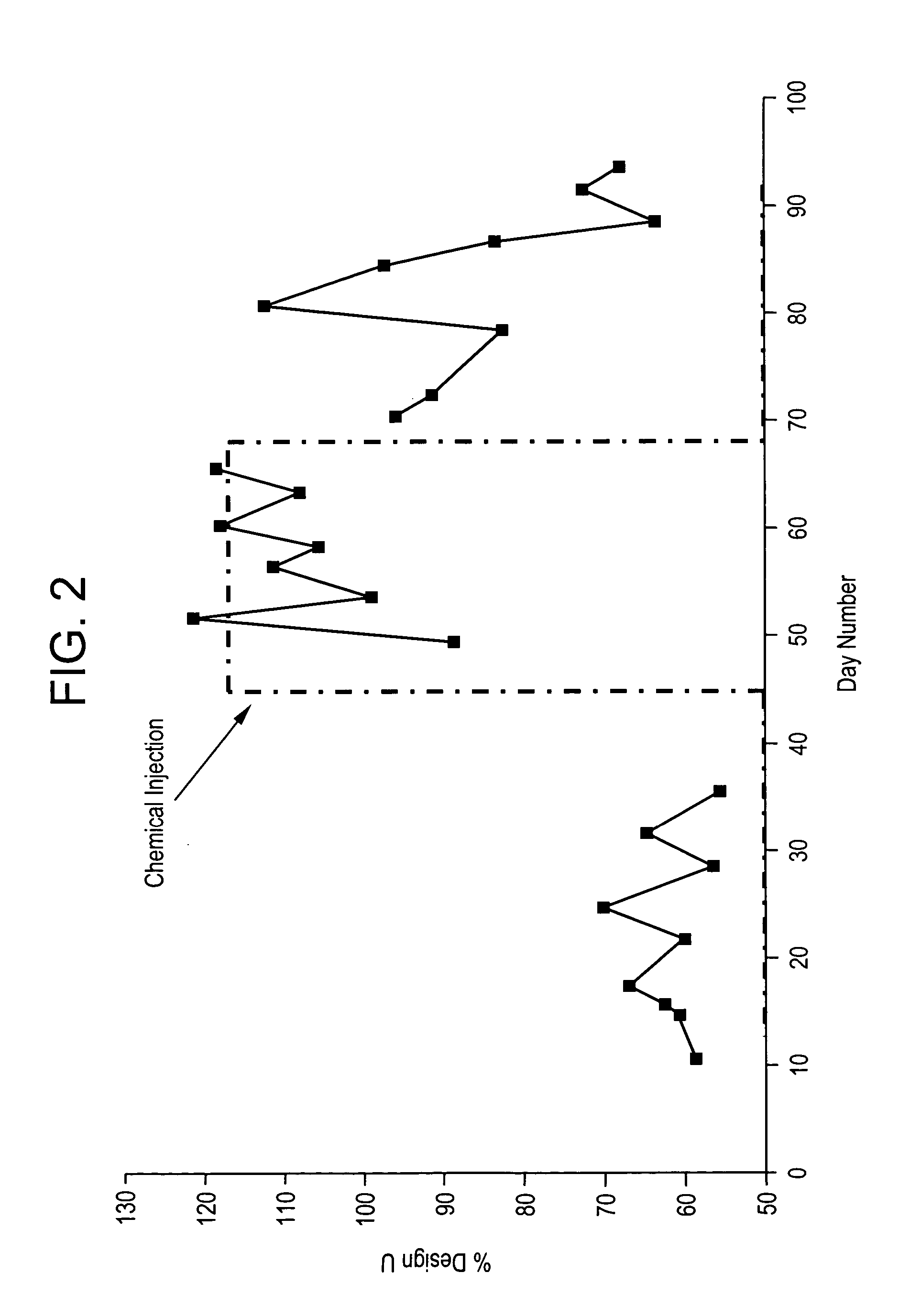
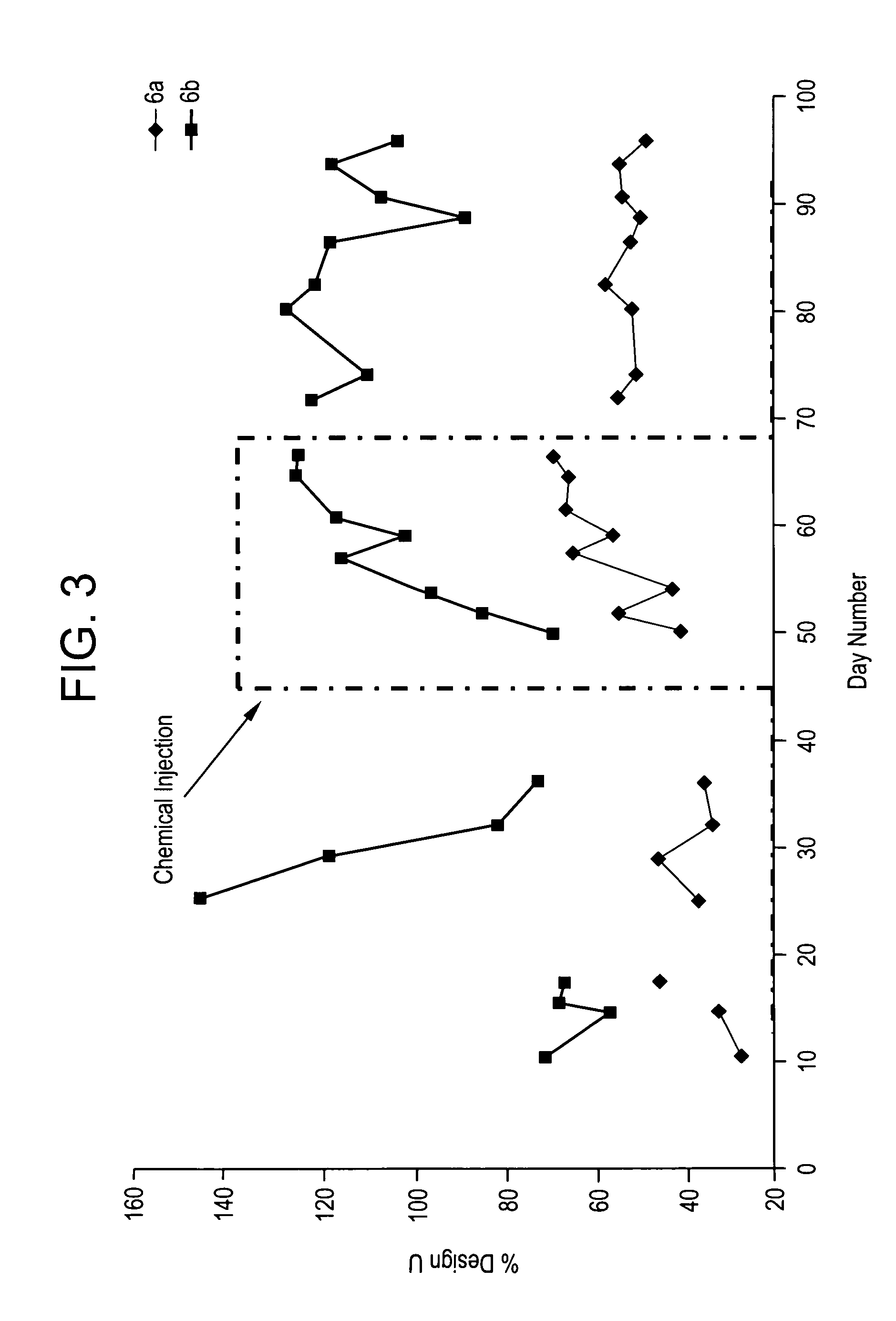
[0064] The trial consists of three phases. The first phase is circulating a solution of 1% DMP in hydrocarbon solvent (injected continuously at two L / minute) through the quench water loop and tower of the ethylene plant to clean the quench tower and heat exchangers. FIG. 1 shows the quench water tower 1 (QWT), the quench water drum separator 2 (QWDS), the fin fan 3 and the heat exchangers 4, 5, 6 and 7. FIGS. 2-5 show the heat transfer efficiencies of the different heat exchangers in the quench loop. The heat efficiency is measured as the percent of the design U coefficient.
[0065]FIG. 2 shows the Fin Fan heat exchanger bank 3 U value data. The bank of fin fans is difficult to isolate, so they are rarely cleaned. As shown in FIG. 2, the fin fans show an immediate and dramatic improvement after the DMP injection begins.
[0066]FIG. 3 shows the data for heat exchangers 6a and 6b. These heat exchangers feed the middle section of the quench tower. ...
PUM
 Abstract
Description
Claims
Application Information
 - R&D
- Intellectual Property
- Life Sciences
- Materials
- Tech Scout
- Unparalleled Data Quality
- Higher Quality Content
- 60% Fewer Hallucinations
Browse by: Latest US Patents, China's latest patents, Technical Efficacy Thesaurus, Application Domain, Technology Topic, Popular Technical Reports.
© 2025 PatSnap. All rights reserved.Legal|Privacy policy|Modern Slavery Act Transparency Statement|Sitemap|About US| Contact US: help@patsnap.com


