
Process for the plasma sterilization of dielectric objects comprising a hollow part

a dielectric object and plasma technology, applied in the field of plasma sterilization of dielectric objects containing hollow parts, can solve the problems of inability to sterilize a large number of polymers, in whole or in part, medical and dental instruments, and long-lasting operations, and achieve the effect of the same sterilization efficiency

Inactive Publication Date: 2005-12-08
VALORISATION RECH LLP
View PDF13 Cites 32 Cited by
  • Summary
  • Abstract
  • Description
  • Claims
  • Application Information

AI Technical Summary

Benefits of technology

[0024] It has been found that the processes of the present invention permit to sterilize contaminated objects having at least one hollow part with very high performance and without degradation of the sterilized objects.
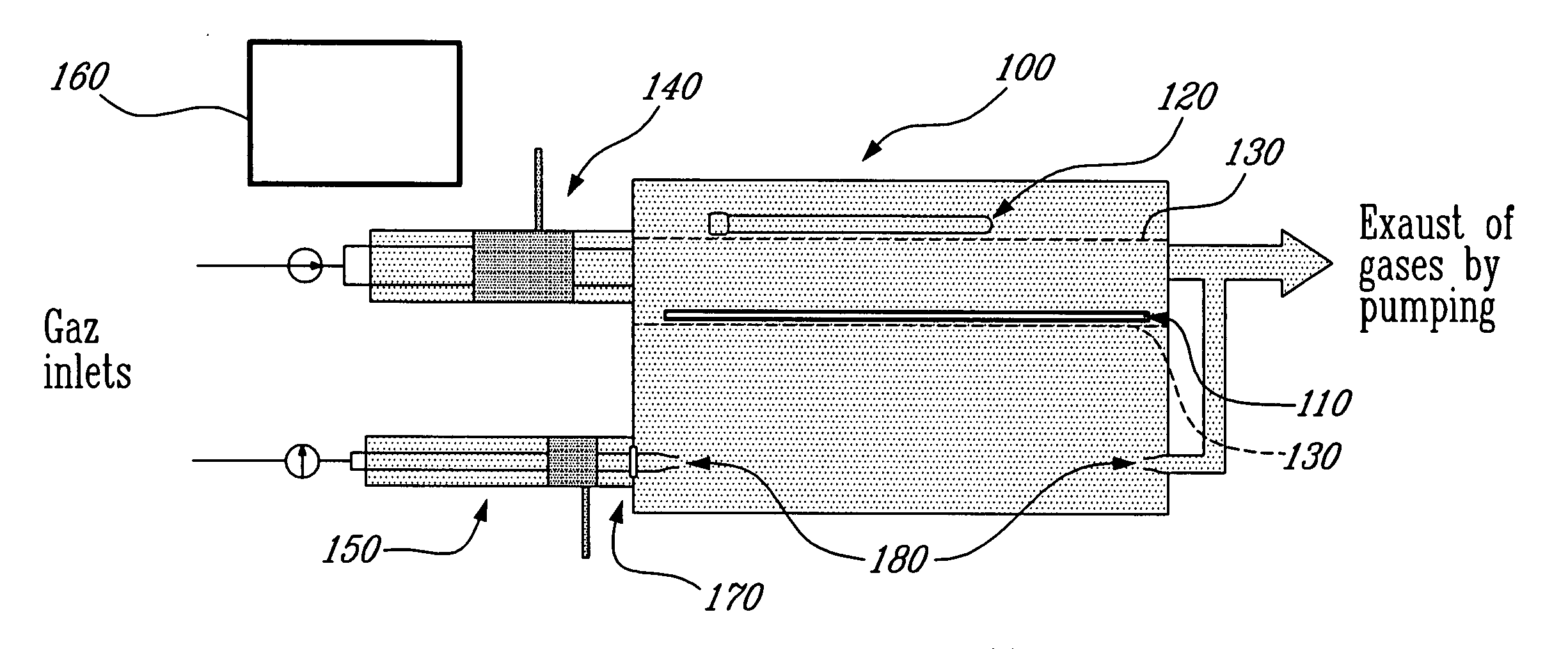
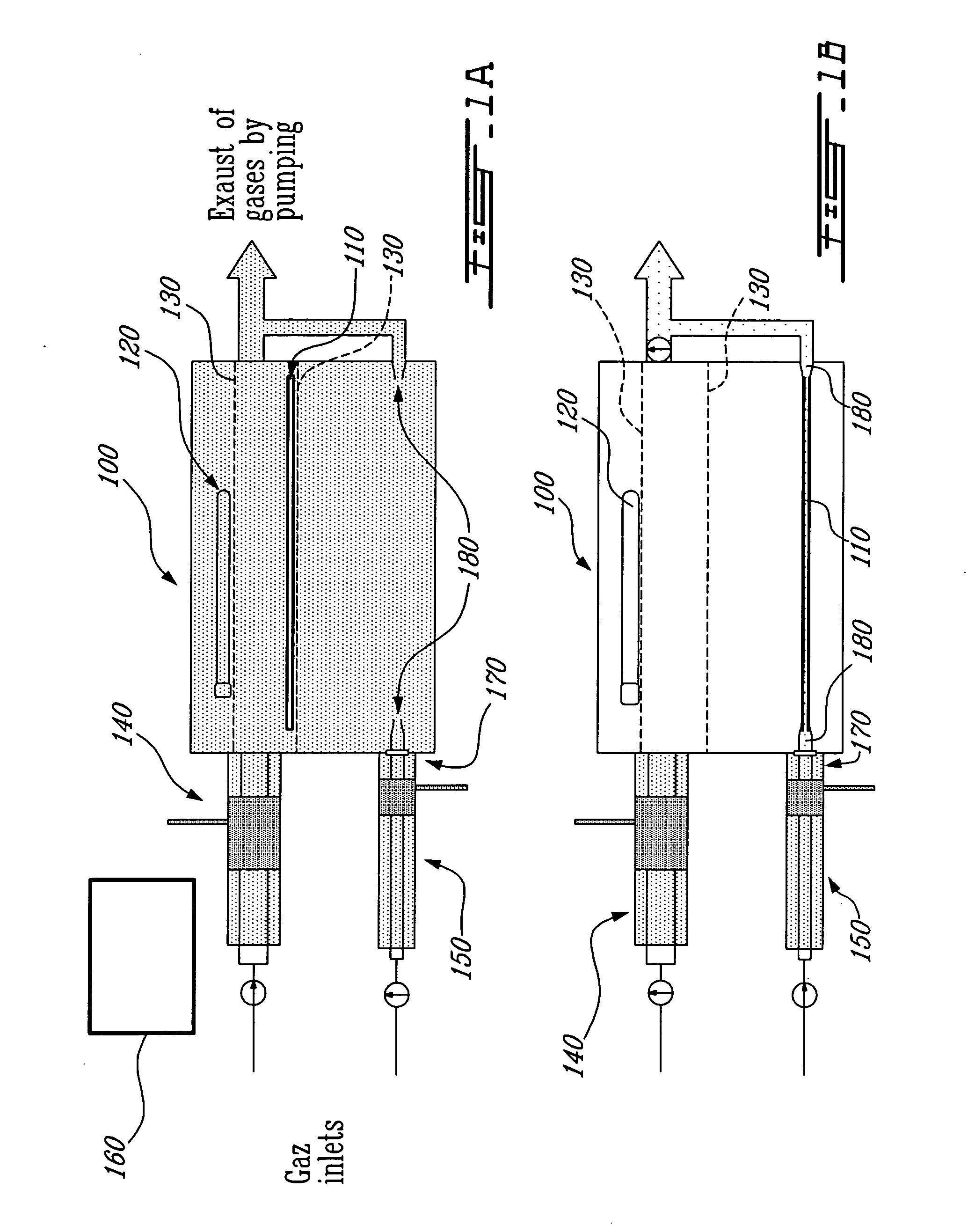
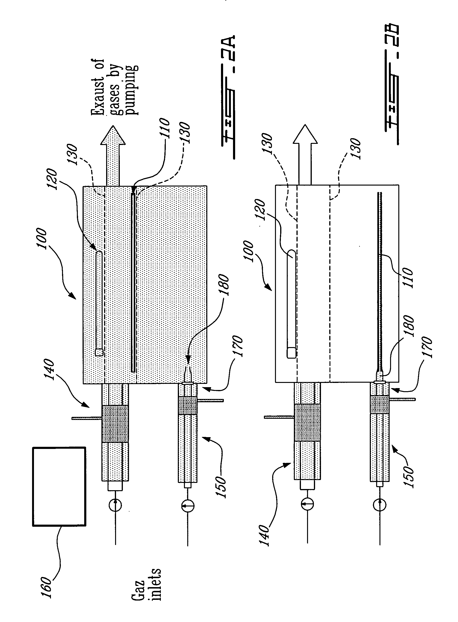
[0131] The process according to the present invention solves this problem by using a gas stream which is nearly stationary (static) and by producing a plasma therein that will be the same all along the discharge tube, thereby ensuring the same sterilization efficiency along a hollow tube, such as an endoscope.

Problems solved by technology

These processes however are disadvantageous in that they significantly cause damage to a large number of polymers that constitute, in whole or in part, medical and dental instruments.
However, in addition to constituting more complex operations, these methods have the disadvantage of being associated with operations that are long lasting.
These processes are indeed of limited application with respect to the disinfection of objects having deep cavities such as ducts.
The reason is that such objects have low hydrodynamic conductance, which makes it difficult to circulate a gas therein, at high speed, a condition that is nevertheless required for using active species (emitters of UV and radicals), with limited life span, which are produced in a plasma source outside the duct (so-called after-glow process), in order that the latter manage to inactivate microorganisms on the entire internal surface of such duct.
On the other hand, a particular limitation with plasma sterilization (whether by exposure in the discharge itself or in its after-glow) resides in the treatment of pre-wrapped objects, which is a common way of dealing with all presently known sterilization techniques.
The nature of these gases, particularly that of fluorinated gases, is often such that an accelerated degradation of the treated objects if to be foreseen.

Method used


Image

  • Process for the plasma sterilization of dielectric objects comprising a hollow part
  • Process for the plasma sterilization of dielectric objects comprising a hollow part
  • Process for the plasma sterilization of dielectric objects comprising a hollow part

Examples


example 1

Experimental Assembling and Corresponding Results Concerning the Use of Surface Wave Discharge for the Inactivation of B. subtilis Spores Introduced into a Hollow Tube—FIG. 3.

[0185] This assembling shows how to use the propagation of a surface wave to produce a plasma inside a hollow tube of dielectric material without damaging the latter with heat and how to control the value of the gas temperature of the gas discharge to obtain this result. The temperature of the exterior of the hollow tube is advantageously measured with a thermocouple.

[0186] This embodiment of the process of the invention makes it possible to sterilize the interior of a hollow tube. In FIG. 5, element (1) represents the discharge tube, (2) the cross-section of tube 1 cm long and made of Teflon™, whose interior is contaminated, (3) a robox surface wave exciter and (4) the plasma.

[0187] The high frequency (HF) power input consists of an amplifier controlled by an oscillator, whose frequency is fixed at 100 MHz ...

example 2

Use of Two Different Gases to Carry Out Sterilization

[0192] A) In a first case, pure argon was used to produce, inside the hollow tube, a gas discharge with a power HF of 100 MHz, by propagating a surface wave. The discharge takes place in a quartz tube (molten silica) with 3 mm internal diameter (tube in which sections 1 cm long of a Teflon™ tube, contaminated with B. subtilis, see FIG. 5, were slid). To make sure that the discharge is uniform along the hollow tube, a very small discharge of gas (≦0.3 cm3 / min.) was used. Pressure was fixed at 0.3 Torr, a value that was determined from results obtained in 26 mm tubes described in the publication of M. Moisan, N. Philip, B. Saoudi, entitled “High Performing System and Process for Sterilizing with Gas Plasma at Low Temperature” and in Canadian Application number 2,395,659 filed on Jul. 26, 2002, supposing that the intensity of UV emission directly depends on electronic temperature, which depends on a law of similars in pR (product of...

example 3

Linear Shaped Applicator of Micro-Wave Field Disposed Along the Hollow Tube to be Sterilized and on the Exterior Side Thereof

[0196] First, there is described the block diagram of the principle based on resorting to a linear sterilizing applicator. With reference to FIG. 6, the micro-wave power flux that is transmitted by the generator to the feeding line flows through openings in the structure of the applicator giving rise to an electrical field that allows to provide a discharge in the tube facing it, in parallel fashion. Power that is not used at the end of the applicator is dissipated in a so-called matched charge (in order to avoid a reflection of the EM wave at the end of the applicator). It is possible to imagine such a system wherein the density of the plasma produced is uniform along the tube to be sterilized. The advantage of this system is that it produces a plasma of much lower density than that of the surface wave. Thus, we can use a HF supply operating at 915 MHz and i...


PUM


Abstract

There is provided a process for sterilizing a dielectric contaminated object having at least one hollow part. The process comprises (a) producing a plasma by submitting a gas or a mixture of gases to an electromagnetic field; (b) treating the exterior of the object by means of an after-glow of the plasma; and (c) treating the at least one hollow part of the object by means of a discharge of the plasma, the discharge being produced inside the at least one hollow part. Step (c) is carried out before or after step (b). This process is particularly useful for sterilizing various medical or dental instruments. There is also provided a device for carrying such a process.

Description

CROSS-REFERENCE TO RELATED APPLICATIONS [0001] The present application is a continuation-in-part of PCT international patent application No. PCT / CA2003 / 001867 filed on Dec. 1, 2003, which claims priority on Canadian patent application No. 2,412,997 filed on Dec. 2, 2002. These applications are incorporated herein by reference in their entirety.FIELD OF THE INVENTION [0002] The present invention relates to a process for the sterilization of dielectric objects. More particularly, the invention relates to the plasma sterilization of dielectric objects containing hollow parts. Such objects can be contaminated, as example, with microorganisms and also with non conventional contagious agents such as pathogenic prions. BACKGROUND OF THE INVENTION [0003] Traditionally, in hospital quarters, sterilization of surgical instruments is carried out by impregnating them with fluids having anti-bacterial and / or antiviral effects, such as glutaraldehyde or hydrogen peroxide. [0004] Other methods com...

Claims


Application Information

Patent Timeline
IPC IPC(8): A61L2/14
CPCA61L2/14
Inventor POLLAK, JEROMEMOISAN, MICHELSAOUDI, BACHIRZAKRZEWSKI, ZENON
Owner VALORISATION RECH LLP
Learn More