Resonance converter with voltage regulation and method of driving variable loads

a voltage regulation and variable load technology, applied in the direction of electric variable regulation, process and machine control, instruments, etc., can solve the disadvantage of capacitive sweep-out losses, the effect of efficient driving variable loads

Inactive Publication Date: 2005-12-22
INFINEON TECH AG +1
View PDF13 Cites 28 Cited by
  • Summary
  • Abstract
  • Description
  • Claims
  • Application Information

AI Technical Summary

Benefits of technology

[0018] It is an object of the present invention to provide a resonance convert...

Problems solved by technology

Switching power supplies with or without a resonance circuit mostly cannot do without inductive electromagnetic devices.
Such components are volume-intensive and cause a significant cost proportion in the overall device.
Even using minority-charge-free MOS (metal oxide semiconductor) transistors, it would have the disadvantage of capacitive sweep-out losses, because the switches have to be switched on under voltage unless an output-side resonance choke lets the voltage rise to about zero across the respective switch when switching on.
If the capacity is, however, chosen too large, the voltage can no longer return to zero, and inadmissible turn-on losses occur.
When employing high-frequency piezoelectric transformers (piezo-transformers) or other energy converters with an electromechanical energy conversion, arbitrary transformation ratios may be realized, but these devices mostly do not offer predominantly inductive input behavior.
Such electromechanical converters are mostly also very narrow-band and can only transfer sinusoidal vibrations with reference to their frequency behavior.
A hard-switching converter topology is therefore less suited for operation thereof.
This limitation to small input voltages has previously mainly been determined by the lacking availability of dynamically quick, high-blocking power switches, which can now be produced inexpensively, e.g. fieldstop IGBT (integrated gate bipolar transistor) up to 1700 V, or cool MOS transistors up to 800 V.
In this case, in an inaccurate fixing of the nominal point, very different output powers arise in applications, such as power supplies, when an adjustment to the phase between the voltages would take place.
Or the value of the output current is sampled accurately enough with great processing overhead.
Phase regulation by sa...

Method used


Image

  • Resonance converter with voltage regulation and method of driving variable loads
  • Resonance converter with voltage regulation and method of driving variable loads
  • Resonance converter with voltage regulation and method of driving variable loads

Examples


Embodiment Construction

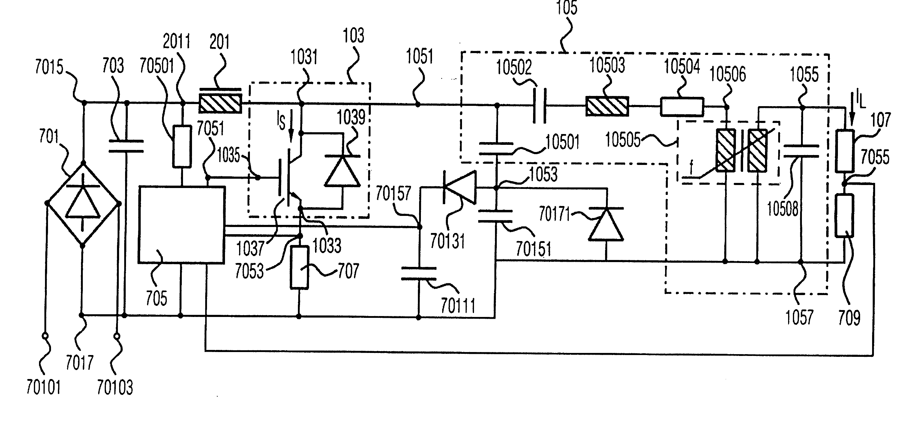
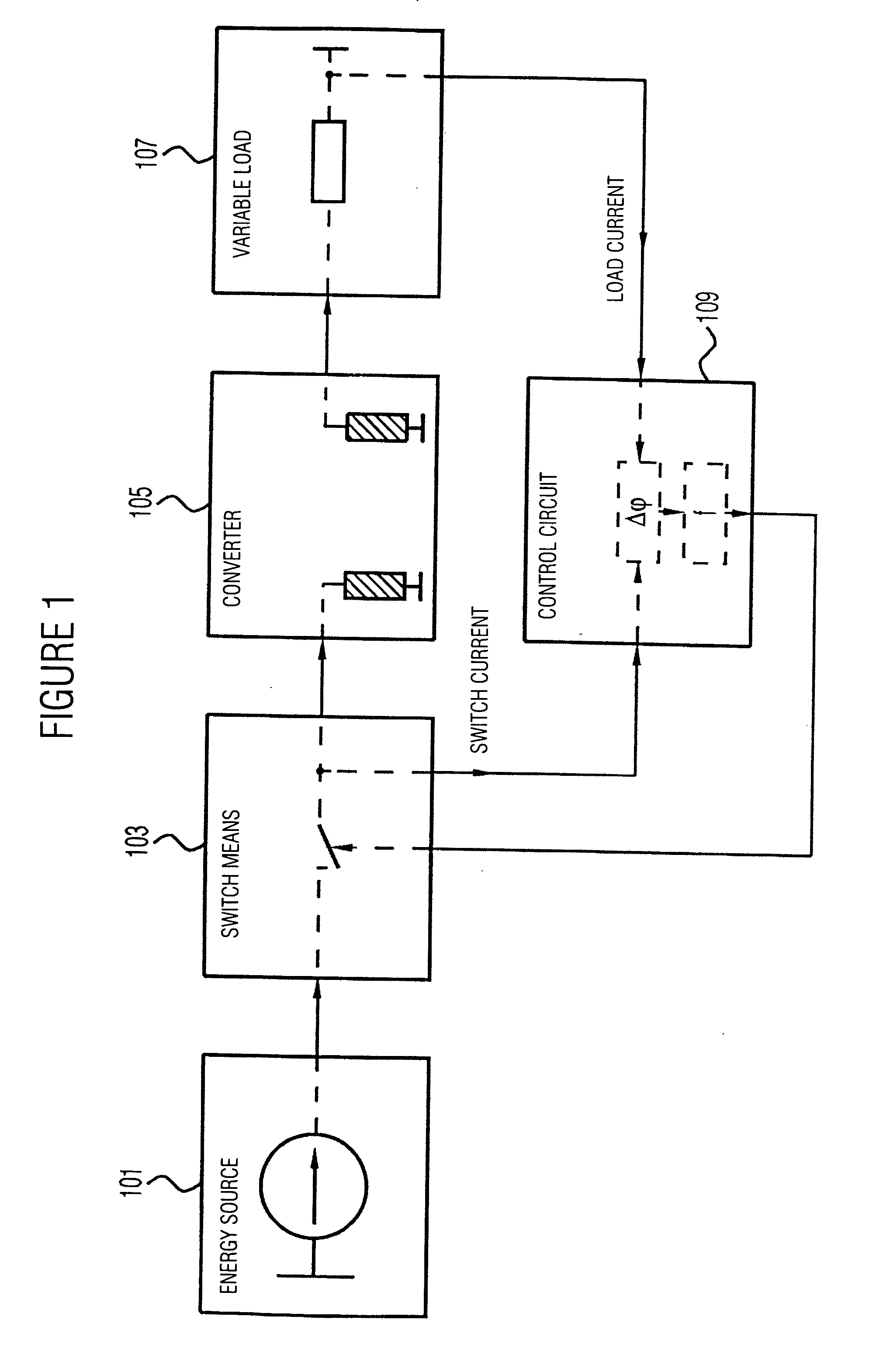
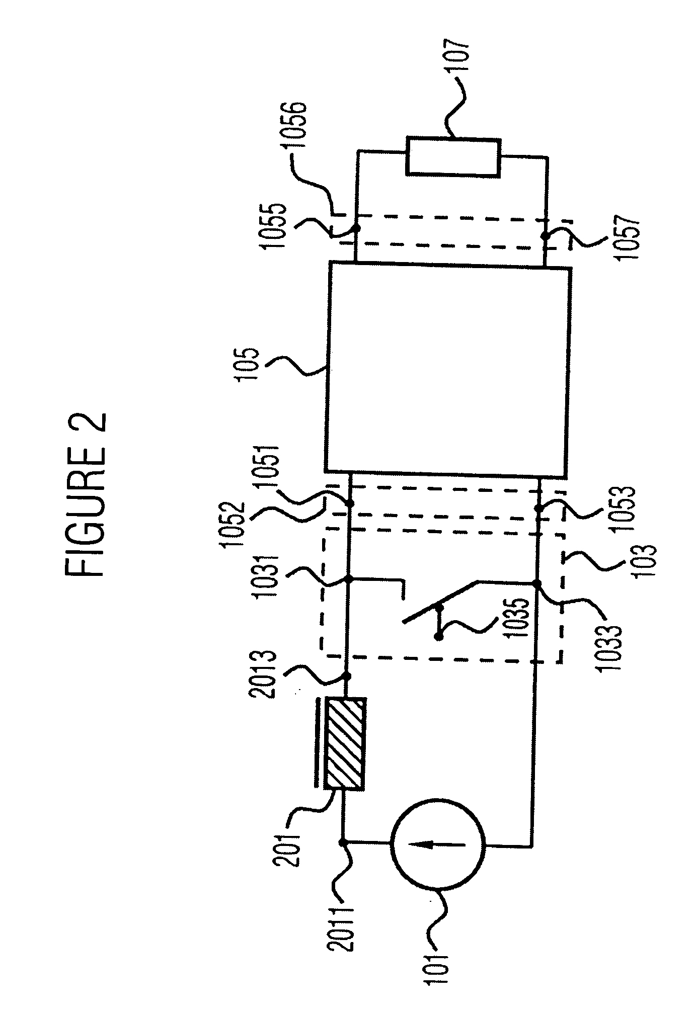
[0043] In FIG. 1 a rough illustration of an inventive resonance converter is shown, which includes a source 101, a switch 103, a piezo-transformer 105, a variable load 107, as well as control means 109. A voltage provided by the source 101 or a current provided thereby is switched by means of the switch 103 at a switching frequency, whereby an input signal is present at the piezo-transformer 105, which is converted to an output signal having a frequency dependent on the switching frequency of the switch 103. This output signal serves for driving a load 107, the load characteristic of which is variable. The switching frequency with which the switch 103 is switched is controlled by the control means 109 on the basis of a phase shift between the current through the switch 103 and the load current through the load 107. This phase shift may be determined from several signals, which may for example be tapped before and after the piezo-transformer 105 as well as before or after the switch ...


PUM


Abstract

In a resonance converter for driving variable loads at first an input signal provided by a switch controlled by control means is converted to an output signal by a transformer. The transformer is dimensioned and connected such that a downward transformation ratio between input signal and output signal is between 5:1 and 100:1 when providing nominal power to the variable load. The switching frequency of the switch is controlled on the basis of a phase shift between a switch current and a load current at variable load and/or variable input voltage, a quantity dependent on the input voltage, as well as a quantity dependent on the output voltage. The inventive resonance converter further enables driving variable loads efficiently with the aid of a transformer.

Description

CROSS-REFERENCE TO RELATED APPLICATION [0001] This application is a continuation of co-pending International Application No. PCT / EP03 / 14428, filed Dec. 17, 2003, which designated the United States and was not published in English and is incorporated herein by reference in its entirety.BACKGROUND OF THE INVENTION [0002] 1. Field of the Invention [0003] The present invention relates to a switching power supply with regulation of the output voltage for driving variable ohmic-capacitive or ohmic-inductive loads, comprising a resonance circuit, an electromechanical energy converter, a switch, and control means. [0004] 2. Description of the Related Art [0005] Switching power supplies with or without a resonance circuit mostly cannot do without inductive electromagnetic devices. For obtaining a low-loss switching operation, such circuits may only be operated up to a certain maximum frequency and only with resonant inductive elements or broadband transformers or inductances. Such components...

Claims


Application Information

Patent Timeline
IPC IPC(8): H02M3/28
CPCH02M3/28Y02B70/1491H02M2001/0058H02M1/0058Y02B70/10
Inventor RADECKER, MATTHIASDEBOY, GERALD
Owner INFINEON TECH AG
Why Eureka
Try Eureka