Tapelike material containing carbon nanotube and production method for cabon nanotube and electric field emission type electrode containing the tapelike material and production method therefor

a technology of carbon nanotubes and carbon nanotubes, which is applied in the manufacture of electrode systems, electrodes/lamps, electric discharge tubes/lamps, etc., can solve the problems of difficult to completely fix the cathode spot, low carbon nanotube content in the product, and a high degree of purity of carbon nanotubes in the product peeled in a tape form, so as to promote peeling the product and increase the purity of carbon nanotubes in the produ

Inactive Publication Date: 2006-01-12
JFEENG CORP
View PDF2 Cites 29 Cited by
  • Summary
  • Abstract
  • Description
  • Claims
  • Application Information

AI Technical Summary

Benefits of technology

[0100] By jetting the gas onto the product to cool the product after carbon nanotubes are produced, as in the above-described aspect (41), the peeling of the product can be promoted. Any cooling gas except combustible gas, such as air or nitrogen, can be used as the jetting gas. The product is formed into a thin film on the surface of the cathode. It is believed that by jetting the gas onto the thin film, the temperature of the film more rapidly decreases than that of the cathode serving as the production substrate, so that thermal stress occurs between the product and the cathode. Thus, peeling significantly proc

Problems solved by technology

Specifically, although carbon nanotubes are produced in a substance constituted of carbon atoms deposited on the carbon cathode of the arc discharge portion, or in part of soot which flied off and deposited in the vicinity of the arc, the above-cited known processes for producing carbon nanotubes cannot prevent the presence of substances other than carbon nanotubes, such as graphite and amorphous carbon, in the product, and the carbon nanotube content in the product is low, accordingly.
Accordingly, synthesis conditions are varied, so that carbon nanotubes may be easily produced in a certain time period, but may be hardly produced or become liable to decompose in another time period.
Unfortunately, it is difficult to completely fix the cathode spot only by adjusting the constituent and pressure of the atmospheric gas and the internal temperature or temperature around the electrodes in the airtight chamber.
Consequently, the yield of the carbon nanotubes is reduced, and a complicated purification process is required to increase the purity of the carbon nanotubes.
Thus, production cost is increased.
Furthermore, the size of equipment is increased to raise equipment costs and make difficult mass production of carbon nanotubes by arc discharge.
However, this process is still intended to continuously collect the deposit on the cathode, containing a large

Method used


Image

  • Tapelike material containing carbon nanotube and production method for cabon nanotube and electric field emission type electrode containing the tapelike material and production method therefor
  • Tapelike material containing carbon nanotube and production method for cabon nanotube and electric field emission type electrode containing the tapelike material and production method therefor
  • Tapelike material containing carbon nanotube and production method for cabon nanotube and electric field emission type electrode containing the tapelike material and production method therefor

Examples


embodiment 1

[0130] The present invention will be further described using embodiments with reference to the drawings.

[0131]FIG. 19 is a schematic illustration of an arc discharge (general discharge) between carbon material electrodes in an argon gas atmosphere under atmospheric pressure. An anode 1 is a bar-shaped carbon material, and a cathode 2 is a plate-shaped carbon material. As shown in FIG. 19, the area where an arc is generated largely moves and the cathode spot also moves irregularly and vigorously on the cathode plate (plate-shaped carbon material 2), in an argon gas atmosphere under atmospheric pressure (FIG. 19 shows two arcs 3a and 3b at different points of time). Reference numeral 4 represents cathode jets where carbon in the cathode evaporates, so that some of carbon atoms ionize. Such vigorous, irregular movement of the arc occurs notably in an argon gas atmosphere under atmospheric pressure, and similar movement is also observed in a helium or hydrogen gas atmosphere under low ...

embodiment 2

[0142]FIG. 4 illustrates a process for producing carbon nanotubes according to Embodiment 2 of the present invention. In the figure, the same parts as in FIG. 1 for Embodiment 1 are designated by the same reference numerals.

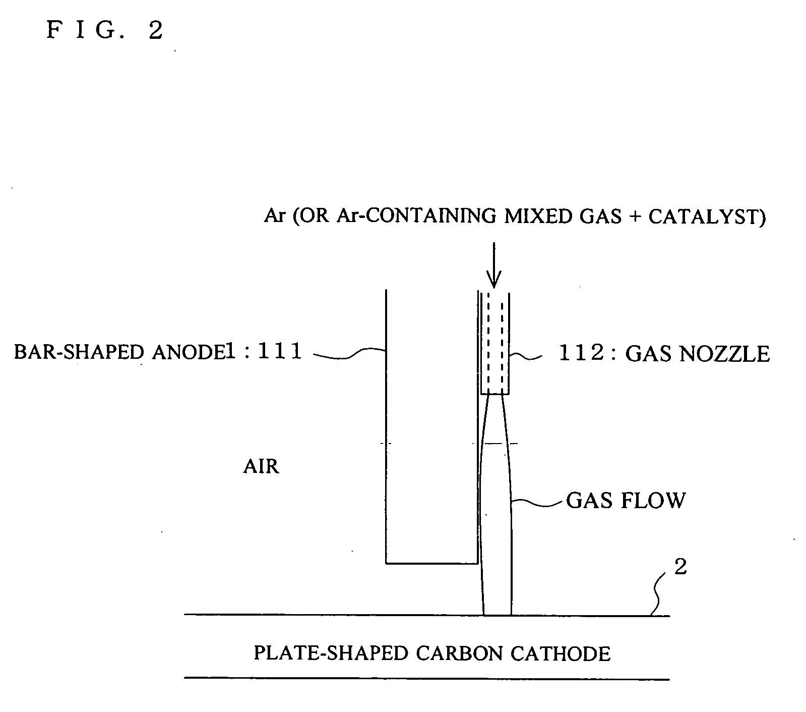
[0143] The process for producing carbon nanotubes according to the present embodiment is characterized in that a catalyst container 22 containing metal or metal compound powder 21 as a catalyst is connected to the same hollow electrode 11 as the anode in Embodiment 1, having a bore 11a around its axis and acting as the carbon material anode, and an arc 3 is generated in an open space (in a normal atmosphere under atmospheric pressure) while a small amount of inert gas, such as argon gas, or inert gas-containing mixed gas is jetted onto the cathode 2 through the catalyst container 22 and the bore 11a of the hollow electrode 11 together with the metal or metal compound powder catalyst 21.

[0144] In the present embodiment also, pure argon or a mixed argon gas conta...

embodiment 3

[0149]FIGS. 6 and 7 show scanning electron micrographs (SEM photographs) of carbon nanotubes produced at the cathode spot, for describing a process for producing carbon nanotubes according to Embodiment 3 in which the cathode is preheated.

[0150] It is considered that in the synthesis of carbon nanotubes by arc discharge, principally, carbon vapor and carbon ions generated from the carbon anode are diffused to the cathode side and condensed at the surface of the cathode having a lower temperature than the anode, thereby producing carbon nanotubes (particularly multi-walled carbon nanotubes). Therefore, in general, the lower the cathode temperature is, the higher the growing speed of carbon nanotubes is, and the cathode is not necessarily formed of carbon material as long as it is heat-resistant and conductive.

[0151] The inventors, however, has found through their experiments that the synthesis ratio of carbon nanotubes cannot be increased only by increasing carbon vapor and carbon ...


PUM

PropertyMeasurementUnit
Temperatureaaaaaaaaaa
Speedaaaaaaaaaa
Speedaaaaaaaaaa

Abstract

A process for producing a tape-like material uniformly containing highly pure single-walled or multi-walled carbon nanotubes with a high density highly pure single-walled or multi-walled carbon nanotubes; a high-performance field emission electrode including the tape-like material; and a process for producing the field emission electrode.
For synthesis of carbon nanotubes by arc discharge, an inert gas or inert gas-containing mixed gas is jetted onto a cathode (2) comprising a carbon material from the inside (11a) of a hollow electrode (11) used as an anode, and simultaneously an arc is generated to form a path of arc discharge along the stream of the gas. Consequently, the cathode spot is prevented from irregularly moving, and thus highly pure carbon nanotubes can be produced. At the same time, by relatively moving both electrodes so as to move the cathode spot of the arc (3) on cathode, the synthesized carbon nanotubes are formed into a tape.

Description

TECHNICAL FIELD [0001] The present invention relates to a process for producing a tape-like material containing highly pure multi-walled or single-walled carbon nanotubes and the highly pure multi-walled or single-walled carbon nanotubes. The invention also relates to a field emission electrode including the tape-like material containing the highly pure multi-walled or single-walled carbon nanotubes, and to a process for manufacturing the same. BACKGROUND ART [0002] Carbon nanotubes (CNT) are produced by arc discharge between two carbon materials, and are graphene sheets, in which carbon atoms are regularly arranged in a hexagonal form, rolled up into cylinders. A single-layer cylinder of a graphene sheet is referred to as a single-walled carbon nanotube (SWCNT), and its diameter is between 1 nm and several nanometers. A cylinder in which a plurality of graphene sheets are concentrically nested is referred to as a multi-walled carbon nanotube (MWCNT), and its diameter is between sev...

Claims


Application Information

Patent Timeline
IPC IPC(8): H05K3/00C01B31/02H01J1/304H01J9/02
CPCB82Y10/00B82Y30/00B82Y40/00C01B31/0233C01B2202/30C01B2202/34Y10S977/844H01J1/304H01J9/025H01J2201/30469Y10T29/49124Y10S977/843C01B2202/36C01B32/162
Inventor NISHI, YASUHIKOMUKAI, HIROTAKAOZAMOTO, DAISUKE
Owner JFEENG CORP
Why Eureka
Try Eureka