Fluid dynamic bearing device

a dynamic bearing and bearing hole technology, applied in sliding contact bearings, mechanical equipment, rotary machine parts, etc., can solve the problems of low strength of manganese sulfide crystals, increased loss torque, and increased power consumption of motors, so as to reduce the surface roughness of bearing holes of sleeves, reduce cost, and reduce surface roughness

Inactive Publication Date: 2006-01-12
PANASONIC CORP
View PDF11 Cites 9 Cited by
  • Summary
  • Abstract
  • Description
  • Claims
  • Application Information

AI Technical Summary

Benefits of technology

[0025] With the present invention, the length, in the axial direction of the bearing hole of the sleeve, of crystals of the free-cutting elements and free-cutting element alloys contained in each free-cutting steel is less than 0.03 mm, and the width in a direction perpendicular to the axial direction is less than 0.005 mm, and as a result, there are almost no fracture planes when the inner peripheral face of the bearing hole of the sleeve is turned on a lathe. Accordingly, there is less surface roughness (bumps) after cutting, and a better cut surface can be obtained. The result is that there is no danger that crystals of free-cutting elements or free-cutting alloys will fall out during the use of the fluid dynamic bearing and make it impossible for the fluid dynamic bearing device to rotate.
[0027] With the present invention, the effect of keeping the carbon content of each free-cutting steel (the material of the sleeve) under 0.1% is that there is a significant reduction in the hard pearlite structure with a Vickers hardness Hv of 500 or higher, which originates in carbon, to the point that substantially no such structure is present. Accordingly, there is much less wear to the rolling balls that form the dynamic pressure generation grooves in the plastic working of the bearing hole of the sleeve.
[0028] With the present invention, the size of the crystals of free-cutting elements and alloys thereof contained in free-cutting steel, ferrite-based free-cutting stainless steel, or martensite-based free-cutting stainless steel is kept small, which reduces the surface roughness of the bearing hole of the sleeve. There is therefore no need for an after-step for reducing surface roughness, which lowers the cost. Also, this lower surface roughness reduces the likelihood that crystals of free-cutting elements will fall out, something which tends to occur during use after the assembly of the fluid dynamic bearing device is completed, so the resulting fluid dynamic bearing device is more reliable.
[0029] Moreover, the carbon content in the free-cutting steel, ferrite-based free-cutting stainless steel, and martensite-based free-cutting stainless steel is kept under 0.1%, and the Vickers hardness Hv of the rod stock of these materials is kept to 230 or less, which greatly extends the service life of the groove rolling tool, and this in turn affords a fluid dynamic bearing device that can be manufactured less expensively.

Problems solved by technology

Since the rotational resistance incurred when the shaft 111 rotates is proportional to the viscosity of the oil, at low temperatures the rotational resistance of the shaft 111 is higher and loss torque increases, resulting in higher power consumption by the motor.
The first problem is that crystals of the free-cutting elements or alloys thereof appear on the surface of the bearing hole 112a that has been turned on a lathe (the dynamic pressure generation grooves 112b have yet to be formed at this point).
Specifically, manganese sulfide crystals are lower in strength and more brittle than low-carbon steel.
With the conventional bearing hole 112a of the sleeve 112, polishing or other such after-working or after-treatment was essential in order to reduce the roughness after lathe turning, but the problem with this was that it drove up the cost.
Another problem arising from manganese sulfide crystals is that some of these crystals fall out during the use of the completed product in which the fluid dynamic bearing has been assembled by inserting the shaft 111 into the bearing hole 112a of the sleeve 112, and this can cause the fluid dynamic bearing to seize.
Specifically, when struck by the tool, the manganese sulfide crystals crack, fall off, and are removed.
Accordingly, microscopic manganese sulfide crystals that have become independent through cracking are present on the surface of a large manganese sulfide crystal, and there is the danger that these may fall off during the use of the product after its assembly.
The inventors conducted various experiments, and found that when a fluid dynamic bearing device is made using a sleeve 112 such as this, microscopic manganese sulfide crystals fall out during use and get into the bearing gap, which makes it extremely likely that the bearing will seize.
This plating does prevent the microscopic manganese sulfide crystals from falling out to a certain extent, and reduces the likelihood of seizure, but it cannot prevent seizure completely.
Because only large manganese sulfide crystals are likely to fall out when the material containing these crystals is cut, a thin plating is not strong enough to adequately prevent the crystals from falling out.
In the conventional example given above, the description was of a case in which low-carbon steel-based free-cutting steel (SUM 24) was used for the material of the sleeve, but since manganese sulfide crystals are usually present when ferrite-based free-cutting stainless steel or martensite-based free-cutting stainless steel is used, the same problems occur with these materials as well.
This is a problem in that the cost of machining the dynamic pressure generation grooves 112b is high.
Because of the high hardness, though, it is disadvantageous in terms of the wear of the rolling balls 124.

Method used


Image

  • Fluid dynamic bearing device
  • Fluid dynamic bearing device
  • Fluid dynamic bearing device

Examples


first embodiment

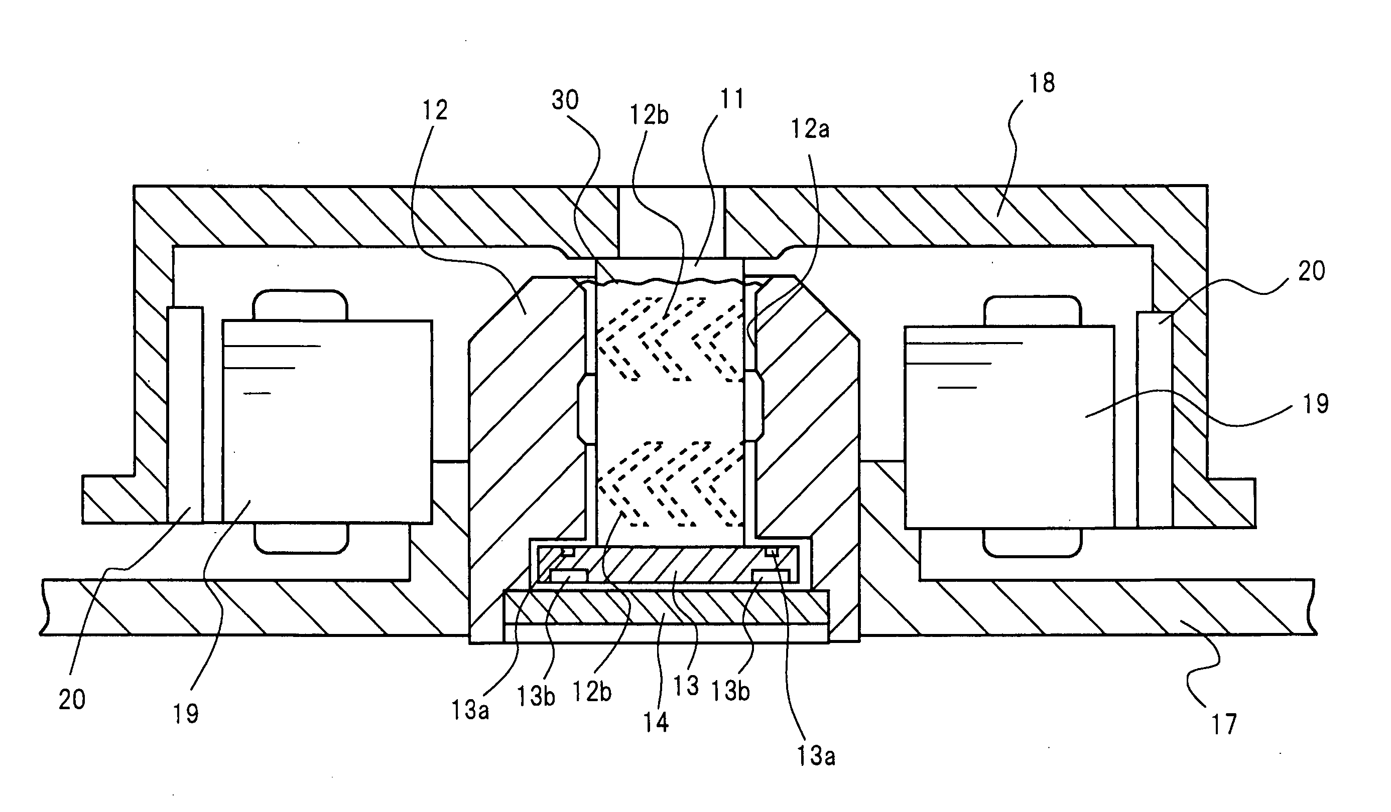
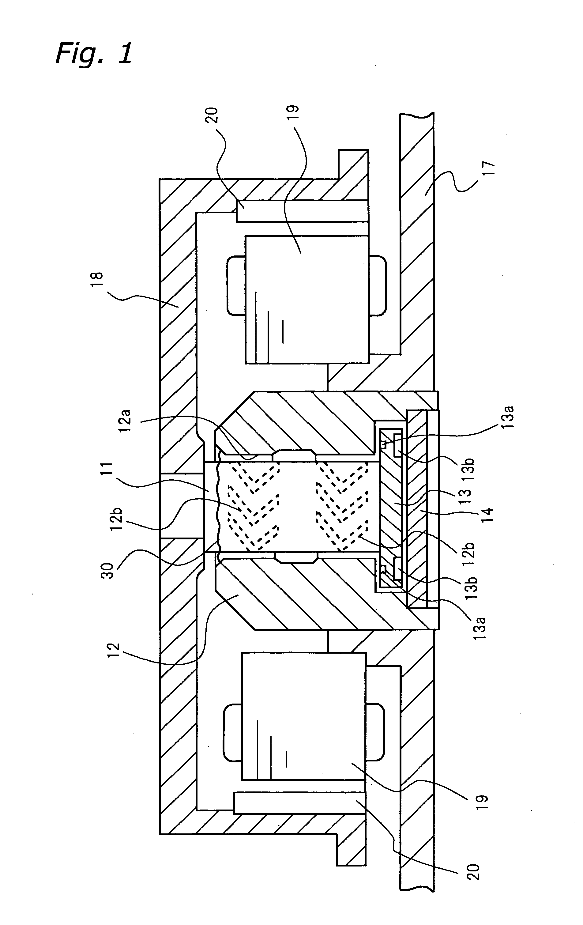
[0045] The fluid dynamic bearing device of the first embodiment of the present invention will be described through reference to FIGS. 1 to 4. The present invention relates mainly to the material of the sleeve of a fluid dynamic bearing. FIG. 1 illustrates a fluid dynamic bearing device that is substantially the same in structure as the conventional fluid dynamic bearing device shown in FIG. 8, except that the various elements are numbered differently. In FIG. 1, a shaft 11 is rotatably inserted in a bearing hole 12a of a sleeve 12. The shaft 11 has a flange 13 formed integrally at the lower end in FIG. 1. The flange 13 is housed in a stepped portion of the sleeve 12, which is attached to a base 17, and the flange 13 is rotatably provided across from a thrust plate 14. A rotor hub 18 to which a rotor magnet 20 is fixed is attached to the shaft 11. A motor stator 19 located across from the rotor magnet 20 is attached to the base 17. Dynamic pressure generation grooves 12b are provided...

second embodiment

[0057] The fluid dynamic bearing device of the second embodiment of the present invention will be described through reference to FIGS. 5 to 7. This second embodiment relates to the material of the sleeve 12, and more particularly relates to the hardness of the material.

[0058] The step of forming the dynamic pressure generation grooves 12b on the inner peripheral face of the bearing hole 12a of the sleeve 12 in the first embodiment is performed using the apparatus shown in FIG. 5, which has substantially the same structure as the apparatus shown in FIG. 12 and described in the “Background Art” section. In FIG. 5, a known groove rolling tool 22 for the plastic working of the dynamic pressure generation grooves 12b is made up of a shank 23, a plurality of rolling balls 24, and a holder 25 for holding the rolling balls 24 on the shank 23. The diagonal length L of the rolling balls 24 is set to be greater than the inside diameter of the bearing hole 12a of the sleeve 12 by a length corr...


PUM

PropertyMeasurementUnit
widthaaaaaaaaaa
widthaaaaaaaaaa
roughnessaaaaaaaaaa

Abstract

A fluid dynamic bearing device is disclosed in which, in the materials used for the sleeve of the fluid dynamic bearing device, particles of free-cutting elements and free-cutting alloys added to iron-based free-cutting steel, ferrite-based free-cutting stainless steel, and so on are reduced in size to about 0.1 to 0.5 μm. The result is smaller crystals of free-cutting alloy, and particularly manganese sulfide, on the inner peripheral face of the bearing hole of the sleeve made of free-cutting steel, which makes the inner peripheral face of the sleeve smoother. Also, the carbon content of free-cutting steel is kept to 0.1% or less, which lowers the hardness of the material and extends the service life of the tool used to cut the dynamic pressure generation grooves.

Description

BACKGROUND OF THE INVENTION [0001] 1. Field of the Invention [0002] The present invention relates to a fluid dynamic bearing device that utilizes the dynamic pressure of a fluid. [0003] 2. Background Information [0004] In recent years, recording devices that make use of a rotating recording medium, such as a magnetic disk, have been increasing in both memory capacity and data transmission speed. Consequently, the bearing devices of disks and the like used in this type of recording device need to rotate at high speed and high precision. It is for this reason that fluid dynamic bearing devices are used as bearing devices (see Japanese Laid-Open Patent Application H05-312212, for example). [0005] A conventional fluid dynamic bearing device will now be described through reference to FIGS. 8 to 12. [0006]FIG. 8 is a cross section of a typical conventional example of a spindle motor equipped with a fluid dynamic bearing device. The fluid dynamic bearing device is shown in the middle part ...

Claims


Application Information

Patent Timeline
Patent Type & Authority Applications(United States)
IPC IPC(8): F16C32/06C22C38/36
CPCF16C17/107F16C33/12F16C33/107F16C2204/60
Inventor HAMADA, TSUTOMUASADA, TAKAFUMI
Owner PANASONIC CORP
Why Eureka
Try Eureka