Pattern-dependent error counts for use in correcting operational parameters in an optical receiver

a technology of optical receivers and error counts, applied in the field of forward error correction systems, can solve problems such as data errors in data signal recovery at optical receivers, and achieve the effect of accurate approach to adjustment of eye pattern threshold and sampling tim

Active Publication Date: 2006-01-12
INFINERA CORP
View PDF20 Cites 64 Cited by
  • Summary
  • Abstract
  • Description
  • Claims
  • Application Information

AI Technical Summary

Benefits of technology

[0012] Therefore, it is an object of the present invention to provide for a more accurate approach for adjustment of eye pattern threshold and sampling time.

Problems solved by technology

The symbols transmitted in predefined time periods eventually spread or overlap into one another due to optical impairments in the transmission lines, such as group velocity dispersion (GVD), as well as due to other system impairments such as interference between DWDM transmitted optical signals, properties of the transmitter, the particular fiber medium or other distortions that may result in data errors in data signal recovery at the optical receiver.

Method used


Image

  • Pattern-dependent error counts for use in correcting operational parameters in an optical receiver
  • Pattern-dependent error counts for use in correcting operational parameters in an optical receiver
  • Pattern-dependent error counts for use in correcting operational parameters in an optical receiver

Examples


Embodiment Construction

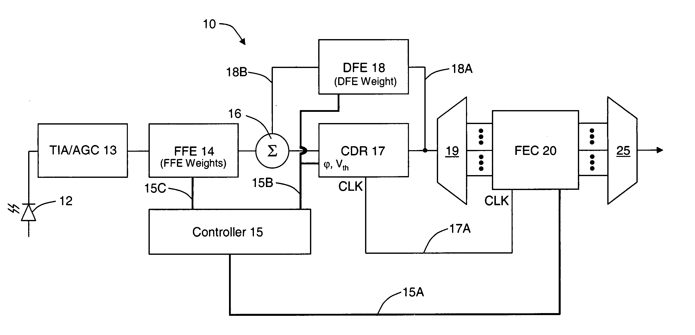
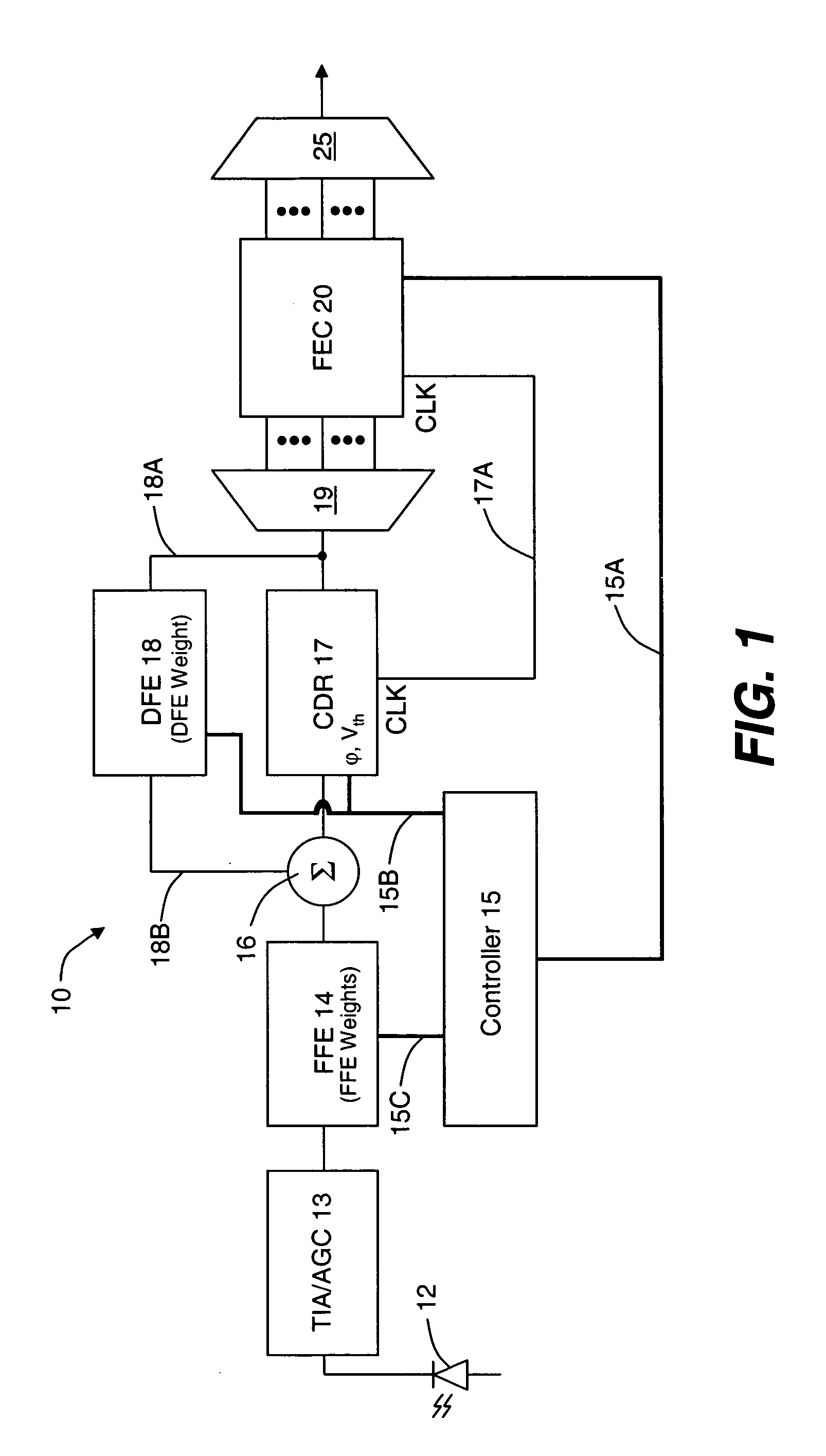
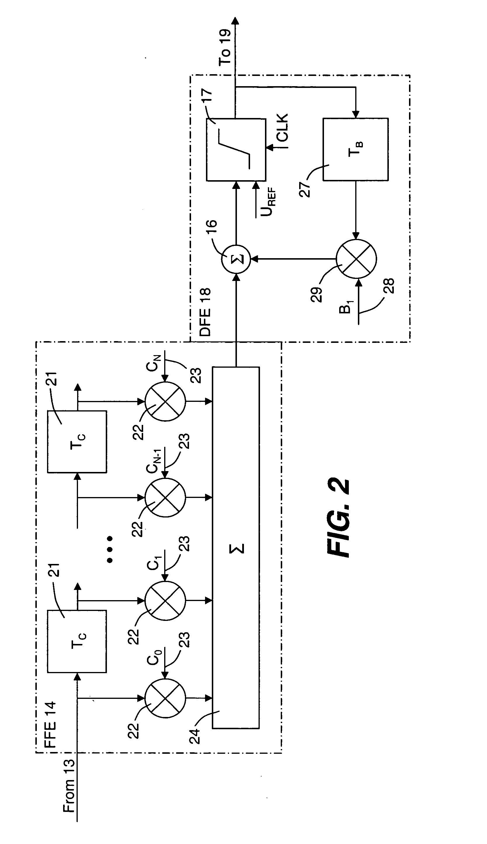
[0043] Reference is now made to FIG. 1 which illustrates a block diagram of an optical receiver 10 that may be utilized in connection with this invention. The receiver 10 has a signal path that includes photodetector 12 where the optical signal is converted into a current signal, the amplitude of which is representative of the optical pulses of the incoming optical channel signal such as in the case of amplitude modulated channel signals. This current signal is then converted into a voltage signal at transimpedance amplifier 13. TIA / AGC 13 also includes an automatic gain control (ADC) circuit to amplify the signal. The signal is then provided to analog transversal filter (TF) or linear feed forward equalizer (FFE) 14, as known in the art and as illustrated in more detail in FIG. 2. FFE 14 provides for correction of transmission impairments to the channel signal, particularly group velocity dispersion (GVD) of the transmitted signal. At the input of FFE 14, the electrical signal is d...


PUM


Abstract

An optical transmission network includes an optical transmitter photonic integrated circuit (TxPIC) chip, utilized in an optical transmitter and has a plurality of monolithic modulated sources integrated for multiple signal channels on the same semiconductor chip is provided with channel equalization at the optical receiver side of the network that permits one or more such integrated modulated sources in the TxPIC chip to be out of specification thereby increasing the chip yield and reducing manufacturing costs in the deployment of such TxPIC chips. FEC error counts at the FEC decoder on the optical receiver side of the network includes counters that accumulate a plurality of bit pattern-dependent error counts based on different N-bit patterns in the received data bit stream. The accumulated counts of different N-bit patterns are utilized to provide for corrections to threshold and phase relative to the bit eye pattern as well as provided for weight coefficients for the optical receiver equalization system. The deployment of this type of equalization in a digital OEO REGEN network substantially reduces, if not eliminates, the need for dispersion compensating fiber (DCF) or EDFAs in an optical link of the network and enhances the optical receiver tolerance to chromatic dispersion (CD) so that an increase in chip yield is realized for TxPIC chips not operating with acceptable operational parameters, particularly with a desired frequency chirp parameter relative to at least one of the TxPIC modulated sources.

Description

BACKGROUND OF THE INVENTION [0001] 1. Field of the Invention [0002] This invention relates generally to a forward error correction (FEC) system and, more particularly, to an electronic equalizer providing auto feedback of both decision threshold and phase offset adjustments for the decision circuit in an optical receiver of an optical transmission network as well as adjustment of tap weight settings for an equalizer located in the optical receiver. [0003] 2. Description of the Related Art [0004] Forward error correction (FEC) systems are used in optical transmission networks to provide for correction of received data. Intersymbol interference (ISI) occurs along the transmission span or link. As is known in the art, error correction codes operate on groups of information or data bits called symbols where each symbol may be a group of bits or a byte, for example. The symbols transmitted in predefined time periods eventually spread or overlap into one another due to optical impairments...

Claims


Application Information

Patent Timeline
Patent Type & Authority Applications(United States)
IPC IPC(8): H04B10/06
CPCH04L1/20H04B10/6971
Inventor CHIANG, TING-KUANGDOMINIC, VINCENT G.TAYLOR, ROBERT B.
Owner INFINERA CORP
Why Eureka
Try Eureka