Method and system for real-time estimation and prediction of the thermal state of a microprocessor unit

a microprocessor unit and thermal state technology, applied in the field of real-time estimation and prediction of the thermal state of an electronic device, can solve the problems of thermal, inefficient, reducing the integrity of the chip, and not having the capability to extract the spatial distribution of temperatur

Active Publication Date: 2006-01-19
GLOBALFOUNDRIES US INC
View PDF21 Cites 75 Cited by
  • Summary
  • Abstract
  • Description
  • Claims
  • Application Information

AI Technical Summary

Benefits of technology

[0049] Even though the method (and system) exemplarily discussed herein is tuned for an application in the thermal management of a microprocessor, it should be understood that any chemical process industry or manufacturing industry that depends on a critical temperature that is not directly measurable can take advantage of the inventive method.
[0050] Additionally, the present invention can detect a malfunctioning or defective temperature sensor in that the invention can compare the sensor's measured / projected value output with the expected output of the sensor. If there is a large difference between the measured / projected value from the expected value, then the invention can declare the sensor as malfunctioning and the sensor can be removed from the inventive algorithm.

Problems solved by technology

Present computer systems do not have the capability to extract the spatial distribution of temperature (e.g., thermal energy) while accounting for the thermal dynamics of the system.
This is inefficient and can be problematic.
Additionally, sustained power dissipation over a zone can give rise to “hotspots” on the silicon that could reduce the integrity of a chip.
Conservative temperature specification, however, limits the performance of a processor.
The power has a steady (DC) component called “leakage current.” Each clock cycle releases a “quanta of energy packet” distributed in the X-Y plane in the processor circuit layer, thus contributing to an unsteady AC component.
The cumulative effect of AC and DC power dissipation in a processor is a major limiting factor in realizing its full potential performance.
The trend toward increased power dissipation is expected to pose an ever greater challenge to the processor and cooling system design.
However, the execution of instructions causes spatially non-uniform and time varying power dissipation, Q(x,y,t), in a processor where “t” denotes time.
However, embedding a multitude of transistor(diode)-based temperature sensors within the digital electronic circuit not only interferes with the digital circuit design, but also impacts cost, performance and reliability of a processor system.
This is problematic and time-consuming.
It would be a major challenge to integrate all of the analog components with noisy high-speed digital circuits to measure temperatures accurately at many different locations.
Further, bandwidth-limited sensors can provide, at best, a delayed measure (due to its time constant) of the present temperature at a location, and have no ability to predict the temperature characteristics under a given computational load.
Additional propagation delay in the X-Y plane due to thermal capacitance makes the present temperature at an arbitrary location deviate from that of a nearby sensor.
Hence, the use of global ranges or discrete temperature sensors are not optimal.
Further, a 2-3 degree conservative prediction may stifle performance.
Additionally, there is a problem in placing the discrete sensors in the right spot.
Yet another problem, prior to the present invention, has been that placing an alien (e.g., separate) temperature sensing circuit into an optimized digital unit (e.g., a processor, a floating point unit or the like optimized for generations to work at maximum speed) may impair the performance of the processor (e.g., especially specialized chips such as game chips).
Hence, one cannot always place sensors where one likes, and thus estimates of temperature may be required.
That is, there has been no innovation in temperature management of a chip through real time executable estimation and prediction of the chip temperature.

Method used


Image

  • Method and system for real-time estimation and prediction of the thermal state of a microprocessor unit
  • Method and system for real-time estimation and prediction of the thermal state of a microprocessor unit
  • Method and system for real-time estimation and prediction of the thermal state of a microprocessor unit

Examples


Embodiment Construction

[0075] Referring now to the drawings, and more particularly to FIGS. 1A-20, there are shown exemplary embodiments of the method and structures according to the present invention.

Exemplary Embodiment

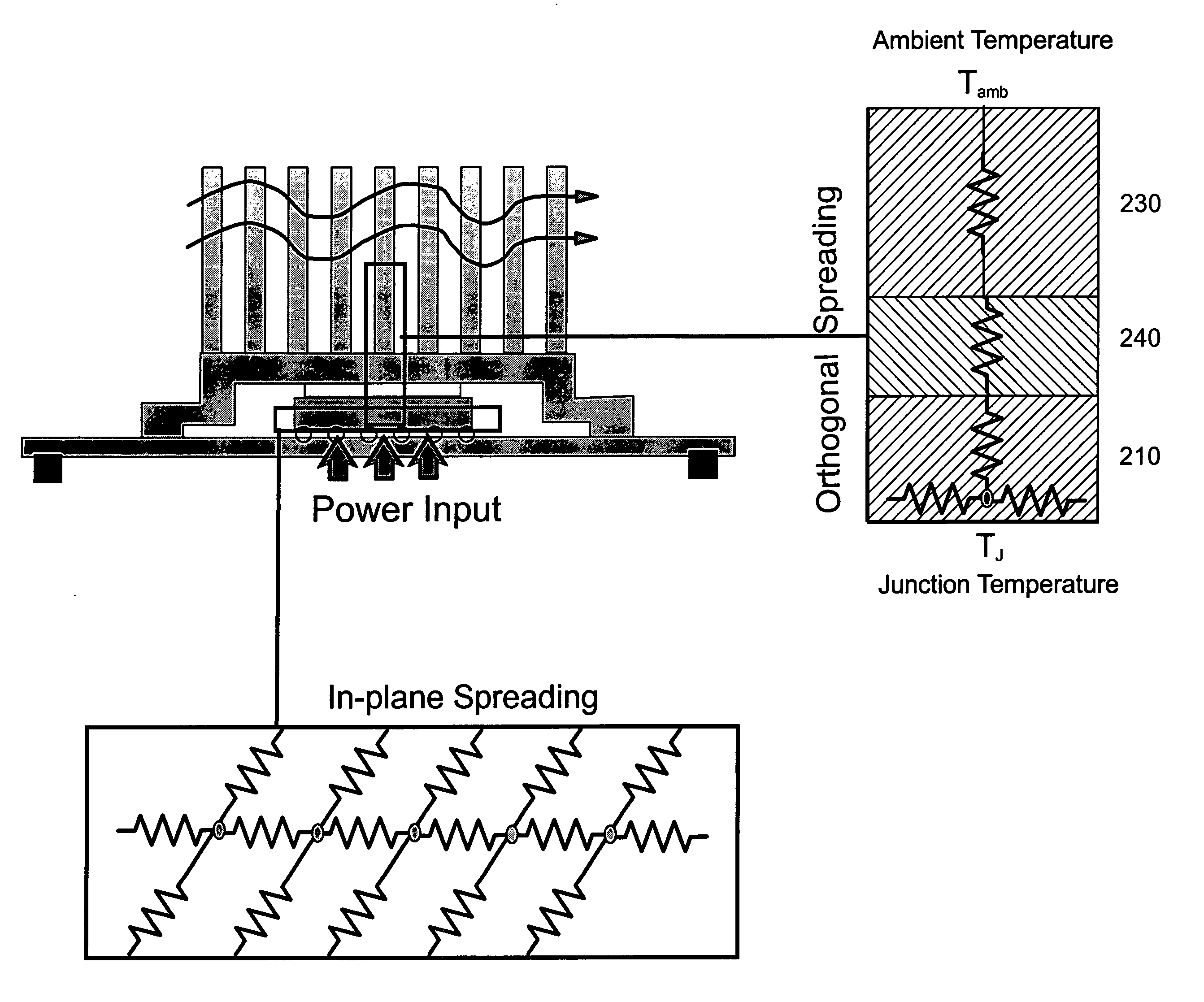
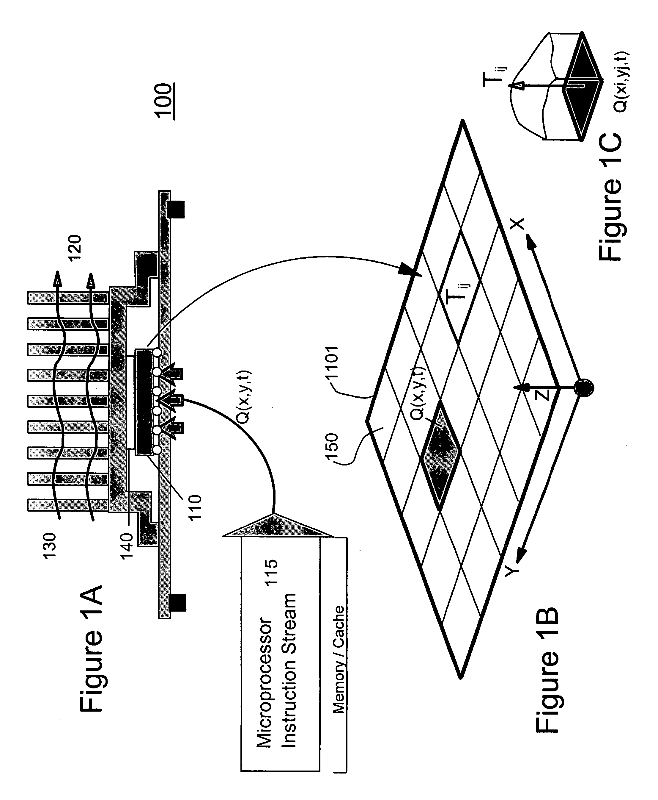
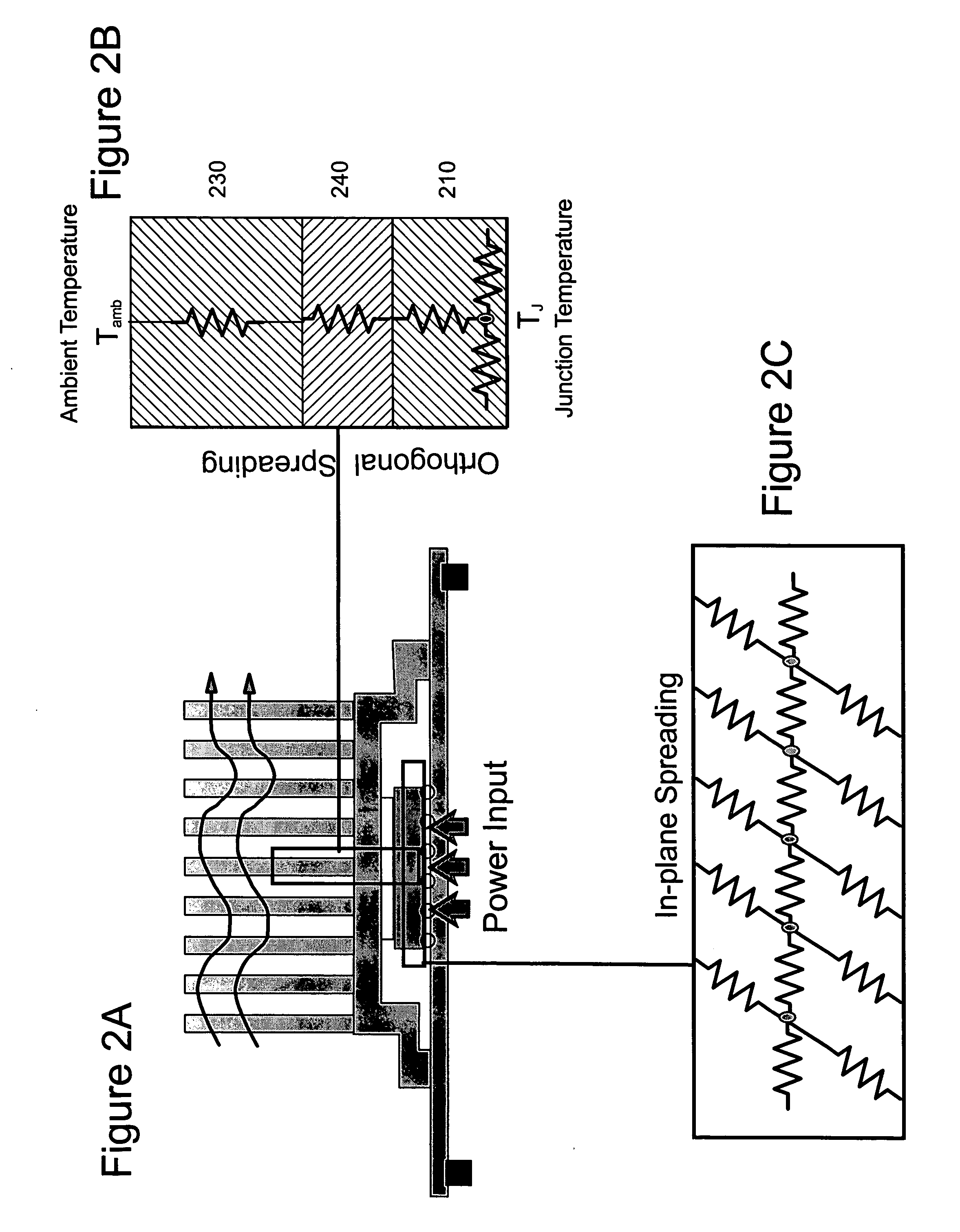
[0076]FIG. 1 A shows a conventional cooling system 100 in which processor circuit 110 switching is driven by a sequence of an instruction set 115, and the heat flux 120 generated by the V(voltage)-I(current) product (due to a transistor switching operation) is eventually conducted to a heat sink 130 through a thermal interface material (TIM) 140. As shown and as understood, the heat flux will be spatially-distributed, unsteady heat flux.

[0077] The processor chip 110 itself is about 20 mm×20 mm in area with a thickness of about 500 um. FIG. 1B shows the bottom of a silicon surface 1101 of the chip 110 with active devices thereon. The heat generating surface 1101 is demarcated by a contiguous set of rectangles or squares 150 in the X-Y plane, as shown in FIG. 1B.

[0078] A lumped paramete...


PUM

PropertyMeasurementUnit
Power consumptionaaaaaaaaaa
thicknessaaaaaaaaaa
thicknessaaaaaaaaaa

Abstract

A method (and system) of predicting a thermal state of a transient thermal system, includes combining sensor outputs and thermal parameters to construct a consistent set of estimates of internal temperature of a transient thermal system.

Description

BACKGROUND OF THE INVENTION [0001] 1. Field of the Invention [0002] The present invention generally relates to a method and apparatus for estimation and prediction of a thermal state of an electronic device, and more particularly to a method and apparatus for real-time estimation and prediction of a thermal state (e.g., global temperature distribution) of a microprocessor unit with a limited set of temperature and current measurements. [0003] 2. Description of the Related Art [0004] Present computer systems do not have the capability to extract the spatial distribution of temperature (e.g., thermal energy) while accounting for the thermal dynamics of the system. [0005] Typically, one or two thermal sensors are used to trigger entry of a processor into a protection mode. As a result, the allowable temperature on the chip is conservatively held lower than necessary, in order to avoid breaching the junction temperature specifications. This is inefficient and can be problematic. [0006] ...

Claims


Application Information

Patent Timeline
Patent Type & Authority Applications(United States)
IPC IPC(8): G01K7/00
CPCG06F1/206G06F1/3203G06F1/324
Inventor SRI-JAYANTHA, SRI M.DANG, HIEN P.SHARMA, ARUN
Owner GLOBALFOUNDRIES US INC
Why Eureka
Try Eureka